Support frame structure for spindle container
A support frame and spindle technology, which is applied to textiles and papermaking, can solve the problems of high cost of plastic bobbins, high production cost, product pollution, etc., and achieve the effect of simple structure, lower sales cost, and convenient exchange.
- Summary
- Abstract
- Description
- Claims
- Application Information
AI Technical Summary
Problems solved by technology
Method used
Image
Examples
Embodiment 1
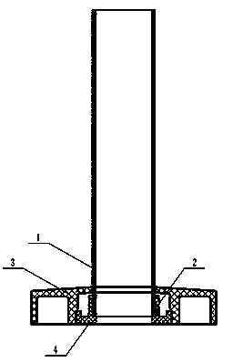
[0041] A supporting frame structure for an ingot drum, comprising a base and a bobbin 1, the base is provided with a locking piece 2, and the bobbin 1 is fixed on the base through the locking piece 2.
[0042] In the present invention, the base is provided with an inlaid cavity, and an inlaid core 4 is provided in the inlaid cavity, the locking member 2 is arranged on the inlay core 4, and the bobbin 1 is fixed on the inlay core 4 through the locking member 2 .
[0043]In the present invention, the base is composed of a chassis 3 and an inlay core 4, the inlay cavity is opened on the chassis 3, and the opening direction of the inlay cavity is downward; the inlay core 4 is inlaid on the chassis 3 through the inlay cavity to form a base; The chassis 3 is provided with a bobbin socket, and the diameter of the bobbin socket is smaller than the diameter of the inlay cavity; the locking member 2 forms a locking hole around the inlay core 4, and the inlay core 4 is also A rotating s...
Embodiment 2
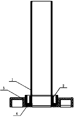
[0052] A supporting frame structure for an ingot drum, comprising a base and a bobbin 1, the base is provided with a locking piece 2, and the bobbin 1 is fixed on the base through the locking piece 2.
[0053] In the present invention, the base is composed of a chassis 3 and an inlay core 4, the inlay cavity is opened on the chassis 3, and the opening direction of the inlay cavity is upward; the inlay core 4 is inlaid on the chassis 3 through the inlay cavity to form a base; The chassis 3 is provided with a rotating shaft jack, the diameter of the rotating shaft jack is smaller than the diameter of the inlay cavity; the locking member 2 forms a locking hole around the inlay 4, and the rotating shaft jack communicates with the locking hole. The hole diameter of the rotating shaft insertion hole is smaller than the outer diameter of the bobbin 1;
[0054] In the present invention, the vertical height of the outer wall of the inlay core 4 is higher than the vertical height of the...
Embodiment 3
[0062] The difference from Embodiments 1 and 2 is that the locking member 2 is equally divided into five arc-shaped locking blocks 6, and the contact surface between each locking block 6 and the bobbin 1 is provided with an anti-slip protrusion 5 .
[0063] When the present invention is in use, the locking member 2 is equally divided into five arc-shaped locking blocks 6, and the five arc-shaped locking blocks 6 cooperate with each other to form a ring shape, and the contact surface between each locking block 6 and the bobbin 1 is uniform. Provided with anti-slip protrusions 5.
PUM
 Abstract
Description
Claims
Application Information
 - R&D Engineer
- R&D Manager
- IP Professional
- Industry Leading Data Capabilities
- Powerful AI technology
- Patent DNA Extraction
Browse by: Latest US Patents, China's latest patents, Technical Efficacy Thesaurus, Application Domain, Technology Topic, Popular Technical Reports.
© 2024 PatSnap. All rights reserved.Legal|Privacy policy|Modern Slavery Act Transparency Statement|Sitemap|About US| Contact US: help@patsnap.com


