Automobile brake failure prevention three-control relay valve

A car brake and anti-failure technology, which is applied in the direction of brakes, brake components, control valves and air release valves, etc., can solve problems such as inability to overlap, damage the vehicle, and weak slow-speed braking torque, and achieve easy installation , Low loading cost, and the effect of increasing the braking torque

Inactive Publication Date: 2014-10-01
CHANGTONG TECH
View PDF11 Cites 0 Cited by
  • Summary
  • Abstract
  • Description
  • Claims
  • Application Information

AI Technical Summary

Problems solved by technology

The fundamental defects of traditional braking technology are: 1. Spring energy storage braking and retarding braking torque are weak, and only control the rear wheel; The dynamic and main brakes cannot be used together
Therefore, when the main brake fails and fails, the emergency efficiency of the traditional braking technology is poor, and the braking force cannot be given in a timely and reasonable manner, and the speed control and parking within the artificial safety range are lost.
[0004]The consequences of brake failure and bad brakes are often major traffic accidents, which are likely to cause casualties, damage to vehicles and damage to public facilities. personal serious harm or loss

Method used


Image

  • Automobile brake failure prevention three-control relay valve
  • Automobile brake failure prevention three-control relay valve

Examples


Embodiment 1

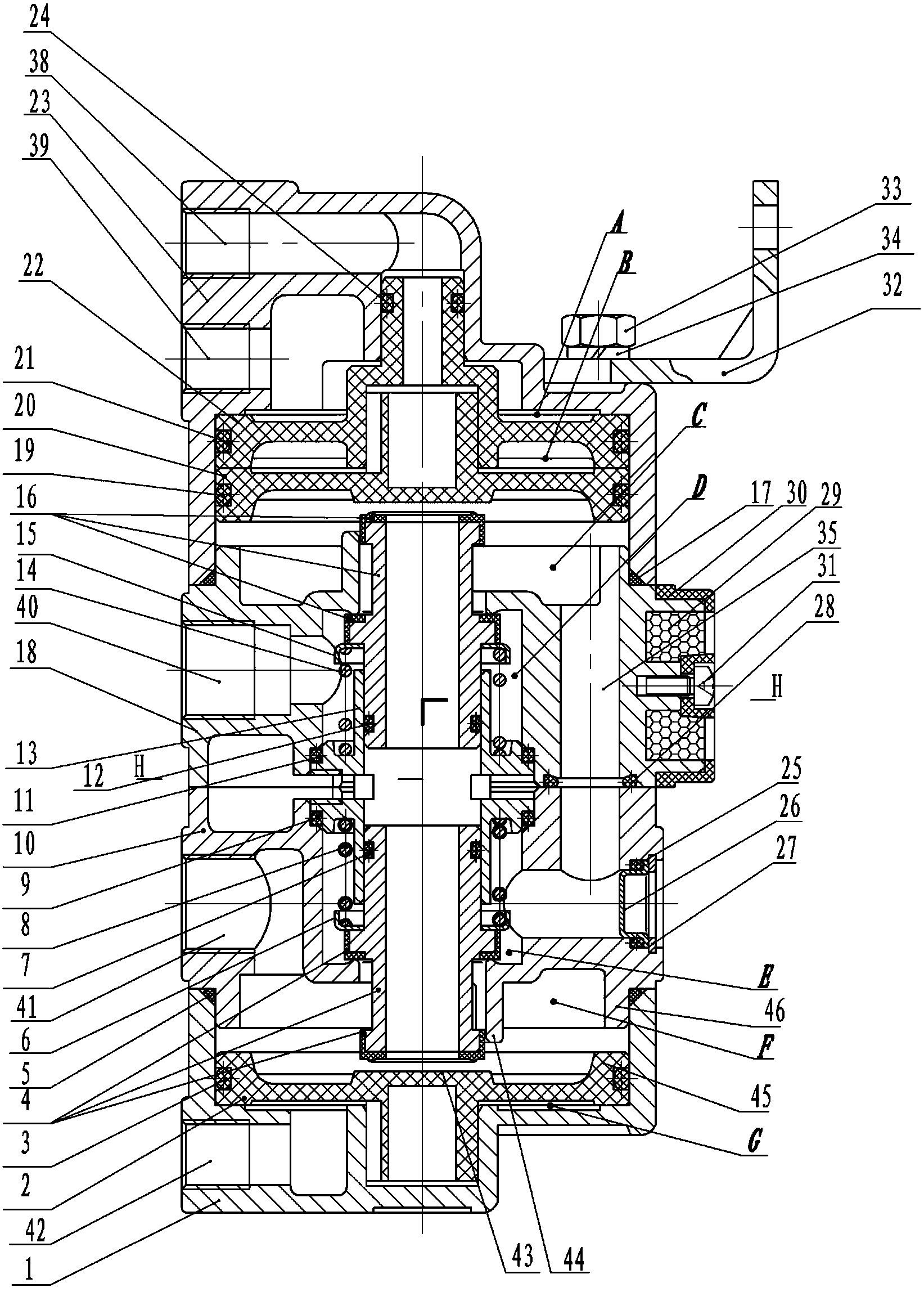
[0023] Embodiment 1: see figure 1 , The automobile brake failure prevention three-control relay valve includes an upper body 23 , a middle and upper body 18 , a middle and lower body 10 and a lower body 1 .

[0024] The upper body 23 is provided with two control air inlets, namely the control air inlet 38 and the control air inlet 39 . The inner cavity of the upper body 23 is sealed with two pistons, that is, a follower piston 20 is installed on the lower side of the upper piston 22. The upper piston 22 is a hollow structure (the piston rod is hollow), and the inner wall of the hollow cavity is provided with steps. Faced as a downward pressing surface, the center column of the follower piston 20 (the center column may be hollow but the bottom is sealed) is set under the step surface in the hollow cavity of the upper piston. The inner cavity of the upper body 23 is separated by two pistons to form a plurality of sealed and isolated air chambers. The upper side of the upper pi...

Embodiment 2

[0031] Embodiment 2, the accompanying drawings are not drawn, the content is basically the same as that of Embodiment 1, and the similarities will not be repeated. The difference is that only one upper piston is arranged in the upper body cavity, and there is no follower piston, so that the upper piston directly drives part. The center of the upper piston is provided with a plug, and the peripheral edge of the upper piston is provided with a limiting flange. The upper piston divides the upper body cavity into upper and lower air chambers, and only one control air inlet is arranged on the upper body, and the control air inlet communicates with the upper air chamber.


PUM


Abstract

The invention discloses an automobile brake failure prevention three-control relay valve, which comprises an upper body, an upper middle body, a lower middle body and a lower body. Air port and air outlet. The anti-failure three-control relay valve of the present invention is one of the components of a braking system. The anti-failure three-control relay valve combines system components to form a braking system, which can achieve blockage due to system failure, component issuance, air pressure reduction and The rapid leakage can compensate the braking torque in a timely and effective manner, which can remedy the front wheel failure, the rear wheel failure and the whole vehicle failure. The invention not only has convenient installation and low loading cost, but also is easy to operate and superior in performance, and remarkably improves the defects of the above-mentioned traditional technology such as braking failure and poor braking. The safety and reliability of the anti-failure braking technology has been improved, which is very conducive to popularization and implementation.

Description

technical field [0001] The invention relates to a relay valve in an automobile braking system, in particular to a failure-preventing three-control relay valve for automobiles. Background technique [0002] Brake failure and failure can be divided into rear axle, front axle and the whole vehicle - because air brake technology is mainly used in medium and large vehicles, and medium and large vehicles are often prone to various reasons such as poor working conditions and defects in traditional braking technology. Cause brake failure, poor braking. For example, various factors such as: low-temperature system pipelines are blocked by water accumulation, system components are frozen and issued, high and low temperature system pipe fittings and components are damaged and leak air, etc., seriously affect the braking reliability. [0003] According to the basic safety requirements of the traditional air brake technology, the following two auxiliary brakes must be provided in additio...

Claims


Application Information

Patent Timeline
Patent Type & Authority Patents(China)
IPC IPC(8): B60T15/18
Inventor 田青锋
Owner CHANGTONG TECH
Why Eureka
Try Eureka