
Flotation column feeding system

A flotation column and ore feeding technology, which is applied in flotation, solid separation, etc., can solve problems such as easy blockage of branch pipes, inconvenient installation work, and installation accuracy that cannot meet the requirements, so as to achieve convenient maintenance and replacement, easy installation accuracy, Effect of Controlling Mounting Accuracy

Inactive Publication Date: 2013-01-09
BGRIMM MACHINERY & AUTOMATION TECH CO LTD +1
View PDF5 Cites 1 Cited by
  • Summary
  • Abstract
  • Description
  • Claims
  • Application Information

AI Technical Summary

Problems solved by technology

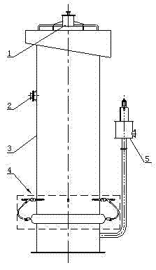
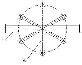
combine figure 2 , for small flotation columns, this kind of ore feeding method can well achieve uniform ore feeding, but for large flotation columns, this kind of ore feeding system has certain limitations: first, the diameter of the flotation column becomes larger Then the number of branch pipes along the circumferential direction of the mine system must be increased, which brings inconvenience to the installation work; secondly, the installation accuracy of the mine system is not easy to control and requires high requirements. If the installation accuracy does not meet the requirements, a large number of branch pipes will There will be some branch pipes that do not flow out of the slurry, and some branch pipes with a large slurry flow rate will be unevenly distributed
Thirdly, the diameter of the branch pipe is relatively small, and there are bends in the shape, while the branch pipe of the large-scale flotation column feed system is relatively long, so it is difficult to realize rubber lining, and the service life of the feed system cannot be guaranteed
Finally, the "claw" type ore feeding system pipe is easy to block and difficult to clean

Method used


Image

  • Flotation column feeding system
  • Flotation column feeding system
  • Flotation column feeding system

Examples


Embodiment Construction

[0019] see Figure 4 , The flotation column feeding system of the present invention comprises a feeding pipe 6, a plurality of pulp outflow pipes 7, a fixing bracket 8 of the feeding pipe, a flange 9 of the feeding pipe, a casing flange 10 and a casing 11 of the feeding pipe; The ore feeding pipe 6 is horizontally inserted into the column body of the flotation column, and the ore slurry is introduced into the flotation column, and is fixed to the column through the connection between the ore pipe flange 9 and the casing flange 10, so as to prevent the entire ore feeding system from rotating, Vibration and swing phenomenon; multiple pulp outflow pipes 7 are arranged on the pipe wall of the ore feeding pipe 6, and multiple ore pulp outflow pipes 7 are arranged obliquely on the ore feeding pipe 6, and multiple ore pulp outflow pipes 7 are distributed on the ore feeding pipe On the wall, the even distribution of the slurry in the mine pipe is realized.

[0020] The ore pipe fixed...


PUM


Abstract

The invention discloses a flotation column feeding system, which comprises a feeding pipe, a plurality of pulp outflow pipes, a feeding pipe fixed support and a feeding pipe casing pipe; the feeding pipe is transversely inserted in a column body of a flotation column and is fixed with the column through a flange; a plurality of pulp outflow pipes are arranged on the pipe wall of the feeding pipe; the feeding pipe fixed support is fixedly installed in the column body and is positioned below the feeding pipe; and the feeding pipe casing pipe and a casing pipe flange are welded into a whole and are then welded on the wall of the flotation column. According to the feeding system provided by the invention, without passing through a feeding branch pipe, pulp is distributed to the flotation column through a pulp outlet directly connected with the feeding pipe, so that the probability that the pulp blocks the feeding system can be greatly reduced; and the feeding pipe is connected with the column body of the flotation column through the casing pipe, so that the installing precision can be easily controlled, the feeding pipe can be conveniently maintained and changed, a rubber liner can be simply installed in the feeding pipe, and the feeding pipe can have longer service life.

Description

technical field [0001] The invention relates to the field of mineral processing, in particular to a flotation column feeding system. Background technique [0002] Flotation column is a kind of mineral processing equipment, which is widely used in the separation of non-ferrous metals, ferrous metals and non-metallic minerals. see figure 1 , the existing flotation column usually consists of a spray water assembly 1, an ore feeding system 2, a column assembly 3, an aeration system 4 and a tailings system 5. When the flotation column is working, the air will generate fine air bubbles slowly rising from the bottom of the column after being acted on by the aeration system 4 installed at the bottom of the column; the ore slurry is fed in from the height of 2 / 3 of the column, and after being evenly distributed by the ore feeding system, Slowly flowing downward; the mineral particles in the pulp and the air bubbles collide countercurrently in the column, and the useful minerals att...

Claims


Application Information

Patent Timeline
Patent Type & Authority Applications(China)
IPC IPC(8): B03D1/16
Inventor 陈东杨文旺武涛余悦董干国
Owner BGRIMM MACHINERY & AUTOMATION TECH CO LTD
Learn More