Automatic cover flipping structure of micro-centrifugal tube

A centrifuge tube and lid technology, which is applied in the field of automatic capping structure of microcentrifuge tubes, can solve the problems of time-consuming, labor-intensive and time-consuming to open the cap, and achieve the effect of saving time and convenient opening.

Inactive Publication Date: 2013-01-09
WUXI NEST BIOTECHNOLOGY CO LTD
View PDF8 Cites 4 Cited by
  • Summary
  • Abstract
  • Description
  • Claims
  • Application Information

AI Technical Summary

Problems solved by technology

[0003] In the existing microcentrifuge tube structure, the cover and the nozzle adopt the method of interference fit. When opening the cover, the cover needs to be manually pulled out from the nozzle of the tube body, which takes time and effort to open the cover and delays time.

Method used


Image

  • Automatic cover flipping structure of micro-centrifugal tube
  • Automatic cover flipping structure of micro-centrifugal tube

Examples


Embodiment Construction

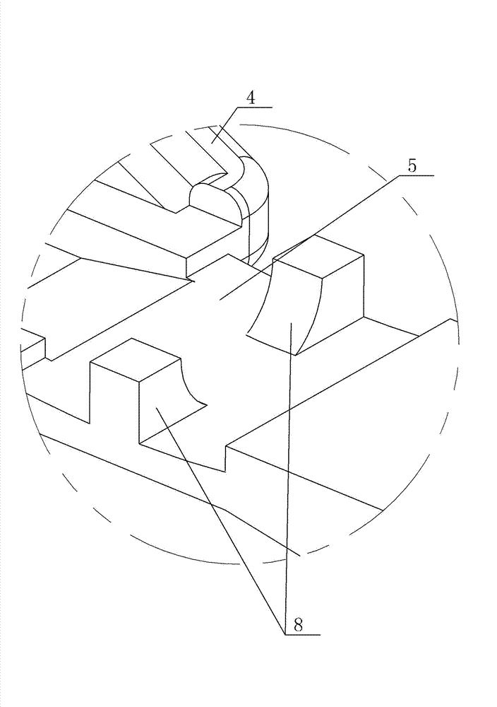
[0009] See figure 1 , figure 2 , which includes a cover 1 and a tube body 2, the cover 1 is mounted on the inner wall of the nozzle 3 of the tube body 2, the outer ring surface 9 of the cover 1 and the inner wall of the nozzle 3 are fitted with an interference fit, and the connecting part of the cover 1 4 Installed on the connecting end 5 of the tube body 2 through the rotating shaft, the outer ring surface of the nozzle 3 is provided with an outer edge positioning protrusion 6, and the cover 1 is provided with a lock 7 at the corresponding position of the outer edge positioning protrusion 6, and is locked. The lock 7 in the locked state is tightly fastened to the lower end surface of the outer edge positioning protrusion 6, and the connecting end 5 of the pipe body 2 is provided with two upward raised structures 8 near the nozzle 3, and the raised structures 8 in the locked state 8 is top mounted on the lower end surface of the corresponding position of the connecting part ...


PUM


Abstract

The invention provides an automatic cover flipping structure of a micro-centrifugal tube. By the automatic cover flipping structure, a cover can be opened conveniently, and time and labor are saved. The automatic cover flipping structure comprises the cover and a tube body, wherein the cover is arranged on the inner wall of an orifice of the tube body in a covering manner, an outer-edge annular surface of the cover clings to the inner wall of the orifice in an interference fit manner, and a connecting portion of the cover is arranged at a connecting end of the tube body by a hinge pin. The automatic cover flipping structure is characterized in that an outer-edge positioning bump is arranged on an outer-edge annular surface of the orifice, the cover is provided with a latch arranged at a position corresponding to the outer-edge positioning bump, the latch fastens the lower end surface of the outer-edge positioning bump when in a locking state, and two upward convex structures are arranged on portions of the connecting end of the tube body close to the orifice, are abutted to lower end surfaces of corresponding positions of the connecting portion of the cover when in locking states, and are of high-elasticity material structures.

Description

technical field [0001] The invention relates to the technical field of cell culture devices, in particular to a structure for automatically flipping a cover of a microcentrifuge tube. Background technique [0002] A microcentrifuge tube is a small centrifuge tube, which is used in conjunction with a microcentrifuge for the separation and centrifugation of micro reagents. It is widely used in biological sciences, especially in the fields of biochemistry and molecular biology. [0003] In the existing microcentrifuge tube structure, the lid and the mouth of the tube adopt an interference fit method. When opening the lid, the lid needs to be manually pulled out from the mouth of the tube body, which takes time and effort and delays time. Contents of the invention [0004] In view of the above problems, the present invention provides a structure for automatically flipping the cover of the microcentrifuge tube, which makes the opening of the cover convenient, saves time and eff...

Claims


Application Information

Patent Timeline
IPC IPC(8): B01L3/14
Inventor 许东良
Owner WUXI NEST BIOTECHNOLOGY CO LTD
Why Eureka
Try Eureka