
Display apparatus

A display device and display unit technology, applied in the direction of light guide, optics, instrument, etc., can solve the problem of display resolution reduction and achieve the effect of expanding the observation area and increasing the number

Active Publication Date: 2013-01-02
JAPAN DISPLAY INC
View PDF10 Cites 10 Cited by
  • Summary
  • Abstract
  • Description
  • Claims
  • Application Information

AI Technical Summary

Problems solved by technology

This display resolution degradation becomes severe as the number of viewpoint images increases

Method used


Image

  • Display apparatus
  • Display apparatus
  • Display apparatus

Examples


Embodiment Construction

[0020] Embodiments of the present invention will be described with reference to the drawings.

[0021] [Overall structure of display device]

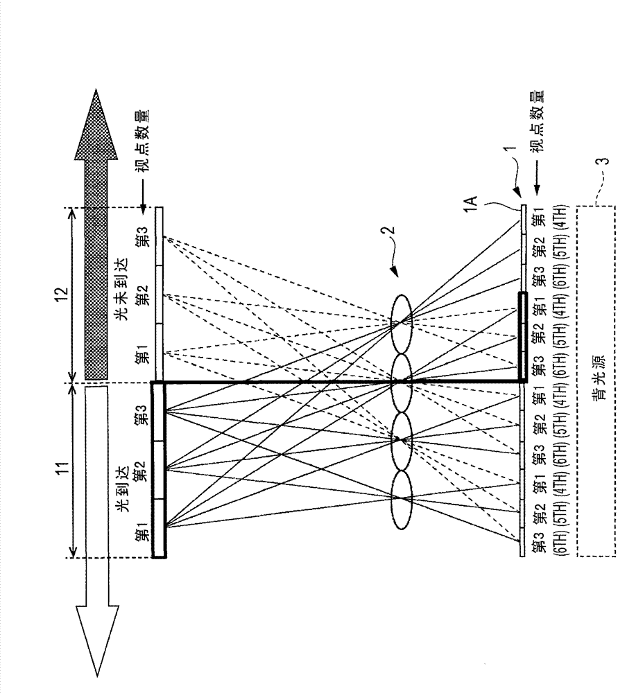
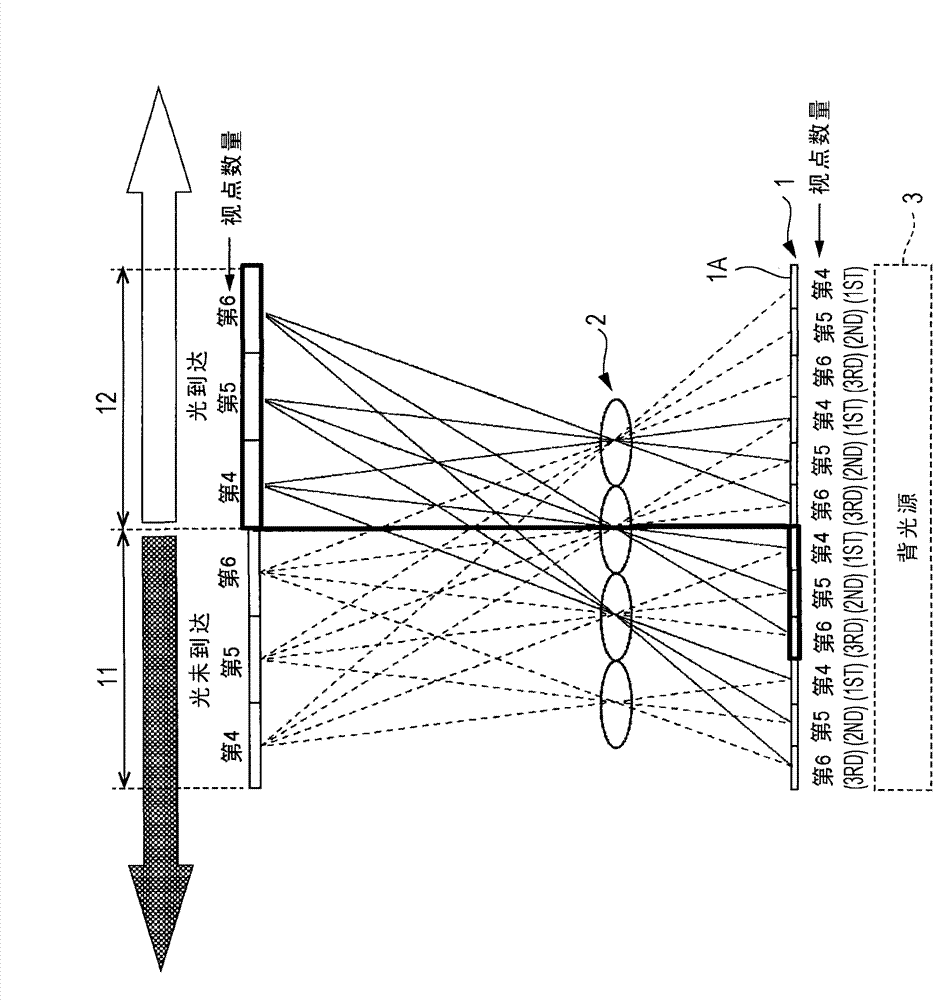
[0022] figure 1 and figure 2 A structural example of a display device according to an embodiment of the present invention is shown. The display device includes a display unit 1 , a lenticular lens 2 as a parallax separation device (separation unit), and a backlight 3 .

[0023] The display unit 1 includes a two-dimensional transmissive display device, for example, the two-dimensional transmissive display device is a transmissive liquid crystal display panel. A plurality of pixels (or sub-pixels) 1A are two-dimensionally arranged on the display screen of the display unit 1 . A plurality of viewpoint images are time-divided and displayed N (an integer equal to or greater than 2) times on the display screen of the display unit 1 .

[0024] exist figure 1 and figure 2 In the example of , the first to sixth viewpoint images are disp...


PUM


Abstract

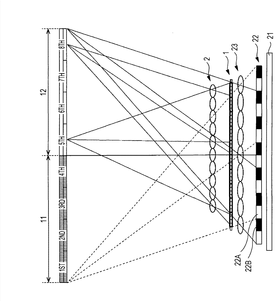
The invention relates to a display apparatus. The display apparatus includes a display unit that time-divisionally displays a plurality of view point images in N divisions, N being an integer equal to or more than 2, a backlight that irradiates the display unit with image display light, and a separation unit that separates M view point images displayed in the same time slot in the display unit, M being an integer equal to or more than 2. The backlight controllably switches the exit direction of light time-divisionally in synch with the timing of time division display by the display unit, the backlight controllably switching the exit direction of light between N directions.

Description

technical field [0001] The present invention relates to a display device that performs stereoscopic display of a naked-eye method by using a parallax separation device such as a parallax barrier. Background technique [0002] There are two types of stereoscopic display methods: a glasses method that uses glasses for stereoscopic viewing, and a naked-eye method that enables stereoscopic viewing with naked eyes without special glasses for stereoscopic viewing. As a general glasses method, there is a shutter glasses method using shutter glasses having a left-eye shutter and a right-eye shutter. In the shutter glasses method, left-eye and right-eye parallax images are alternately displayed in a frame-continuous manner on a two-dimensional display panel at high speed. The left-eye shutter and the right-eye shutter are switched alternately at the moment when the left-eye and right-eye parallax images are displayed, so that the left-eye and right-eye parallax images enter the obse...

Claims


Application Information

Patent Timeline
Patent Type & Authority Applications(China)
IPC IPC(8): H04N13/00G02B27/22G02B30/27
CPCG02B27/22H04N13/045G02B6/0038H04N13/0418H04N13/00G02B27/2214G02B6/0076H04N13/32H04N13/354G02B30/27
Inventor 杨映保滨岸五郎
Owner JAPAN DISPLAY INC
Learn More