Safety protection device for rotation angle of rotary work table

A technology of safety protection device and rotating workbench, which is applied to the direction of workbench and manufacturing tools, and can solve the problems that the limit angle of rotation cannot be further expanded and the path is short.

Inactive Publication Date: 2015-04-22
SPARKING POWER TECH
View PDF8 Cites 0 Cited by
  • Summary
  • Abstract
  • Description
  • Claims
  • Application Information

AI Technical Summary

Problems solved by technology

[0004] see figure 2 , the safety protection device is provided with a pusher 21 on the outer peripheral side of the rotary table 20, and a stopper 23 is erected with a linear guide rail 22 on the outer position corresponding to the pusher 21, and the pusher 21 is used to push the stopper 23 Move along the linear guide rail 22, and set the first light sensor 24 and the second light sensor 25 on the outside of the stopper 23. When the rotary table 20 rotates clockwise, the right side drives the stopper 23 to enter For the first light sensor 24, after the first light sensor 24 receives the sensing signal, the controller will control the rotary table 20 to reverse counterclockwise, so as to avoid exceeding the position of the first light sensor 24, When the rotary table 20 reverses counterclockwise and drives the shifter 23 from the left to enter the second light sensor 25, similarly, the controller controls the rotary table 20 to rotate clockwise to avoid exceeding the second light sensor. The position of the detector 25, the rotation limit angle θ formed by the rotation of the rotary table 20 from the position of the first light sensor 24 to the position of the second light sensor 25 is greater than 360°, although it can improve the aforementioned safety protection device However, the pusher 21 of the safety protection device makes a rotary motion, while the shifter 23 moves horizontally and linearly, so that the superimposed shifting path between the pusher 21 and the shifter 23 Shorter, and can not expand the rotation limit angle

Method used


Image

  • Safety protection device for rotation angle of rotary work table
  • Safety protection device for rotation angle of rotary work table
  • Safety protection device for rotation angle of rotary work table

Examples


Embodiment Construction

[0029] In order to enable your examiner to have a better understanding of the present invention, hereby cite a preferred embodiment together with the accompanying drawings, and describe it in detail as follows:

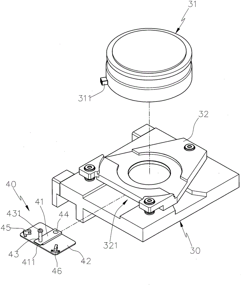
[0030] see image 3 , Figure 4 , the present invention includes a rotary table 31 located on the base 30 and a limit mechanism 40 located on the side of the rotary table 31. In this embodiment, the rotary table 31 is located on a base 32, and the base 32 is set on the base 30 again, wherein, the pedestal 32 is a stepped groove 321 on one side, and the limit mechanism 40 is partly concealed in the stepped groove 321 of the pedestal 32; A pusher 311 is provided, and a swing arm 41 is pivoted on the base 30 by the limit mechanism 40. In this embodiment, a bottom plate 42 fixed on the base 30 is provided, and a pivot 44 is pivoted on the bottom plate 42. Establish a swing arm 41, and on the swing arm 41 corresponding to the position of the pusher 311 of the rotary tabl...


PUM


Abstract

A safety protection device for a rotation angle of a rotary work table comprises the rotary work table arranged on a base and a limit mechanism arranged on the side of the rotary work table, a motion driving member is arranged at an appropriate position on the outer ring side of the rotary work table, a rotary arm of the limit mechanism is pivoted on the base, a motion retaining member is arranged in a protruding mode on the rotary arm and corresponding to the motion driving member on the rotary work table, and therefore the rotary arm can be driven to swing to the left or right respectively when the rotary work table rotates forward or reversely. Additionally, a first sensor and a second sensor are arranged respectively on the route when the rotary arm swings to the left or right, and the rotation of the rotary work table can be controlled within a set angle range when the rotary arm swings to the left or right and triggers the first and second sensors, therefore, continuous rotation of the rotary work table can be limited, a large rotating limit angle can be obtained, and practical benefits can be achieved when various operations are performed on the rotary work table.

Description

technical field [0001] The invention relates to a rotation angle safety protection device which can limit the continuous rotation of a rotary table and obtain a larger rotation limit angle to facilitate various operations on the rotary table. Background technique [0002] The rotary table mainly carries the work object, and drives the work object to rotate and change direction, so as to facilitate various processing operations. One type of rotary table can continuously rotate twice in the same direction because the accessories are completely installed on the table. As mentioned above, continuous rotation is performed. Another type of rotary table is assembled in the rotating shaft or connected to the peripheral side of the table due to the accessory components. In order to avoid the twisting of the accessory components due to rotation, the rotary table is Continuous rotation must be limited. For example, the rotary table used by the wafer cutting machine, because it fixes th...

Claims


Application Information

Patent Timeline
Patent Type & Authority Patents(China)
IPC IPC(8): B25H1/00
Inventor 刘东波
Owner SPARKING POWER TECH
Why Eureka
Try Eureka