
A lithium-ion battery diaphragm automatic retracting device

A lithium-ion battery, automatic winding technology, used in transportation and packaging, thin material processing, sending objects, etc., can solve the problems of irregular shape of the diaphragm, incomplete incision of the diaphragm, no incision of the diaphragm, etc., to achieve convenient operation. , to avoid the effect of incomplete cutting and waste of resources

Inactive Publication Date: 2021-06-25
湖南润沅新材料有限公司
View PDF4 Cites 0 Cited by
  • Summary
  • Abstract
  • Description
  • Claims
  • Application Information

AI Technical Summary

Problems solved by technology

[0003] Most of the lithium-ion battery separators currently on the market often have a cutting device that can only cut one width of the separator when they are collected, but they often require different widths of the separator when they are used, so they have to be cut off when they are used. It causes a waste of resources, and some tapes are easy to shake during collection, which leads to entanglement during collection. The machine has to stop, resulting in production stagnation, and then manual repairs, wasting a lot of time and resources, and some devices are not fixed. The device of the diaphragm may lead to incomplete cutting during cutting, and various situations often occur during winding, such as: the diaphragm is not cut, resulting in failure to collect during collection, and some diaphragms are incompletely cut , causing the diaphragm to be torn apart under the mutual pull of the tape, resulting in irregular shape of the diaphragm and making it unusable, etc. Therefore, a lithium-ion battery diaphragm automatic retracting device is proposed to solve the above problems

Method used


Image

  • A lithium-ion battery diaphragm automatic retracting device
  • A lithium-ion battery diaphragm automatic retracting device
  • A lithium-ion battery diaphragm automatic retracting device

Examples


Embodiment 1

[0028] Example 1: See Figure 1-11 , the present invention provides a technical solution:

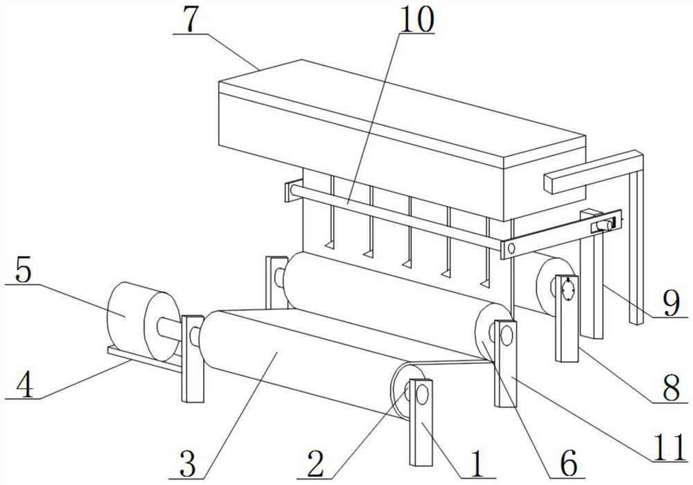
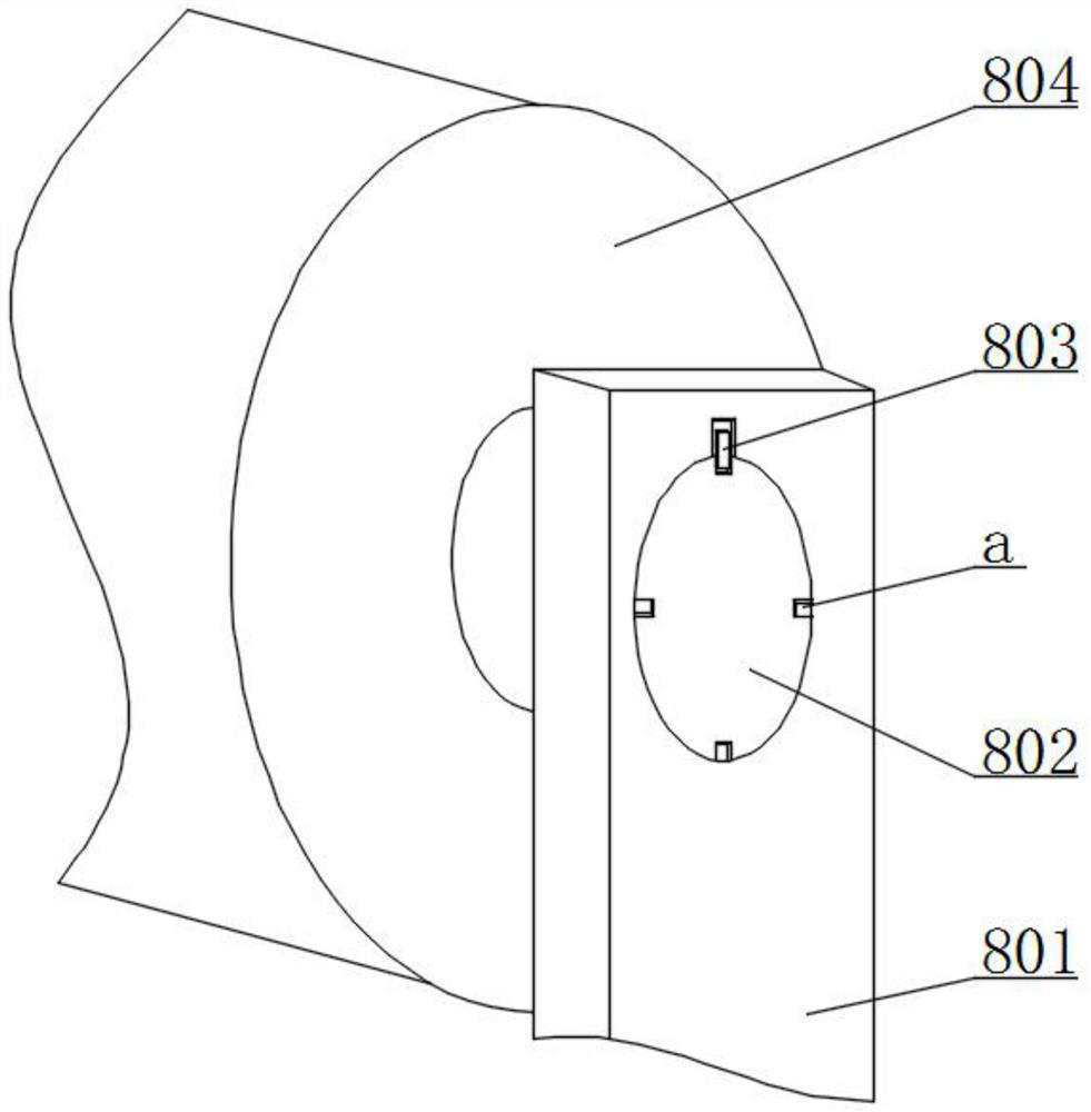
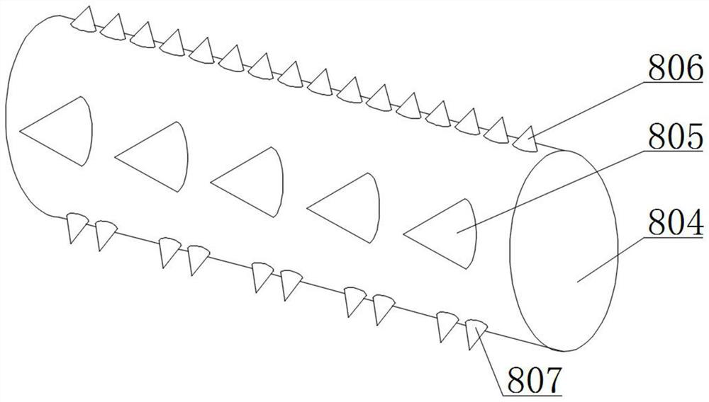
[0029]An automatic retracting device for a lithium-ion battery diaphragm, comprising a first bracket 1, a rotating shaft 2, a lithium-ion battery diaphragm 3 and a fixed plate 4, a rotating shaft 2 is rotatably connected above the right end surface of the first bracket 1 on the right side, and the rotating shaft 2. There is a lithium-ion battery separator 3 on the outside. This setting can ensure that the lithium-ion battery separator 3 will not wrinkle and ensure the quality of the lithium-ion battery separator 3. The left end of the first bracket 1 on the left is fixedly connected with a fixing plate 4, and the upper end surface of the fixed plate 4 is fixedly connected with the first motor 5, the end of the main shaft of the first motor 5 is fixedly connected with the rotating shaft 2, the fourth bracket 11 is arranged behind the first bracket 1, and the right end surface of the four...

Embodiment 2

[0032] Example 2: See Figure 1-11 , the present invention provides a technical solution:

[0033]An automatic retracting device for a lithium-ion battery diaphragm, comprising a first bracket 1, a rotating shaft 2, a lithium-ion battery diaphragm 3 and a fixed plate 4, a rotating shaft 2 is rotatably connected above the right end surface of the first bracket 1 on the right side, and the rotating shaft 2. There is a lithium-ion battery separator 3 on the outside. This setting can ensure that the lithium-ion battery separator 3 will not wrinkle and ensure the quality of the lithium-ion battery separator 3. The left end of the first bracket 1 on the left is fixedly connected with a fixing plate 4, and the upper end surface of the fixed plate 4 is fixedly connected with the first motor 5, the end of the main shaft of the first motor 5 is fixedly connected with the rotating shaft 2, the fourth bracket 11 is arranged behind the first bracket 1, and the right end surface of the four...

Embodiment 3

[0036] Example 3: See Figure 1-11 , the present invention provides a technical solution:

[0037]An automatic retracting device for a lithium-ion battery diaphragm, comprising a first bracket 1, a rotating shaft 2, a lithium-ion battery diaphragm 3 and a fixed plate 4, a rotating shaft 2 is rotatably connected above the right end surface of the first bracket 1 on the right side, and the rotating shaft 2. There is a lithium-ion battery separator 3 on the outside. This setting can ensure that the lithium-ion battery separator 3 will not wrinkle and ensure the quality of the lithium-ion battery separator 3. The left end of the first bracket 1 on the left is fixedly connected with a fixing plate 4, and the upper end surface of the fixed plate 4 is fixedly connected with the first motor 5, the end of the main shaft of the first motor 5 is fixedly connected with the rotating shaft 2, the fourth bracket 11 is arranged behind the first bracket 1, and the right end surface of the four...


PUM


Abstract

The invention relates to the technical field of lithium-ion battery diaphragms, in particular to an automatic retracting device for lithium-ion battery diaphragms, comprising a first bracket, a rotating shaft, a lithium-ion battery diaphragm and a fixing plate, and the first bracket on the right side rotates above the right end surface A rotating shaft is connected, and a lithium-ion battery diaphragm is arranged on the outside of the rotating shaft. A fixing plate is fixedly connected to the left end surface of the first bracket on the left side, and a first motor is fixedly connected to the upper surface of the fixing plate. The end of the main shaft of the first motor It is fixedly connected with the rotating shaft, a fourth bracket is provided behind the first bracket, and a winding shaft is connected to the right end surface of the fourth bracket in rotation, and a lithium-ion battery diaphragm is arranged under the winding shaft; in the present invention, through the provided first A limit pin, take-up disk and the second motor effectively avoid the situation that the diaphragm cannot be wound up and the winding is uneven, ensure the normal operation of the device, avoid the waste of resources, and save a lot of time. This setting has huge Economic benefits are worth promoting.

Description

technical field [0001] The invention relates to the technical field of lithium-ion battery diaphragms, in particular to an automatic retracting device for lithium-ion battery diaphragms. Background technique [0002] In the structure of lithium batteries, the diaphragm is one of the key inner components. For the lithium battery series, since the electrolyte is an organic solvent system, it is necessary to have a diaphragm material resistant to organic solvents. Generally, high-strength thin-film polyolefin porous The performance of the diaphragm and diaphragm determines the interface structure and internal resistance of the battery, which directly affects the capacity, cycle and safety performance of the battery. A diaphragm with excellent performance plays an important role in improving the overall performance of the battery. The main function of the diaphragm is to enable The positive and negative poles of the battery are separated to prevent short circuit caused by contac...

Claims


Application Information

Patent Timeline
Patent Type & Authority Patents(China)
IPC IPC(8): B65H35/02
CPCB65H35/02
Inventor 陈亚丽蒲明良
Owner 湖南润沅新材料有限公司
Learn More