Distributing device of piston-pusher centrifuge

A technology for distributing devices and centrifuges, which is applied to centrifuges and centrifuges with rotating drums, etc. It can solve the problems of reducing the stability and production capacity of centrifuges, reducing product quality, and unbalanced centrifuges, so as to improve The scope of application and the stability of use, easy maintenance, and reliable operation

Inactive Publication Date: 2013-01-02
蒋立峰
View PDF8 Cites 9 Cited by
  • Summary
  • Abstract
  • Description
  • Claims
  • Application Information

AI Technical Summary

Problems solved by technology

[0002] The main part of the currently widely used two-stage pusher centrifuge has the following unfavorable factors: 1. When there are strict requirements on the crushing rate of the separated material particle size, it has a great impact on the crushing rate and reduces the product quality; 2. When The separated material is viscous, the concentration of the suspension is too high, and the particle size of the material is too small, which will cause uneven distribution, which will cause greater vibration of the centrifuge, greatly reducing the stability and production capacity of the centrifuge; 3. When the particle size of the separated material Too small; accumulation will form between the pusher disc and the first-stage pusher drum, which will cause the centrifuge to be unbalanced, or even damage the centrifuge. For this kind of accumulation, it is often necessary to stop the machine to remove the residual filter residue manually, or use a large amount of washing Liquid flushing, but the effect is not ideal; Chinese patent application number 200920300587.2 discloses a device for flushing holes on the collection shell of a pusher centrifuge, but the above shortcomings still exist to varying degrees, and the above problems cannot be solved from the structure of the centrifuge

Method used


Image

  • Distributing device of piston-pusher centrifuge
  • Distributing device of piston-pusher centrifuge
  • Distributing device of piston-pusher centrifuge

Examples


Embodiment Construction

[0012] The present invention will be further explained below in conjunction with the drawings

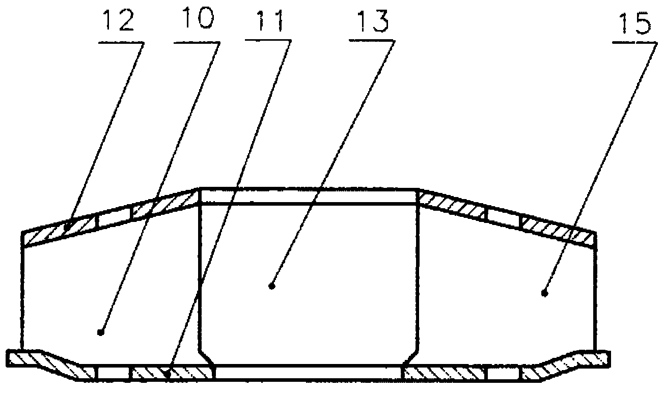
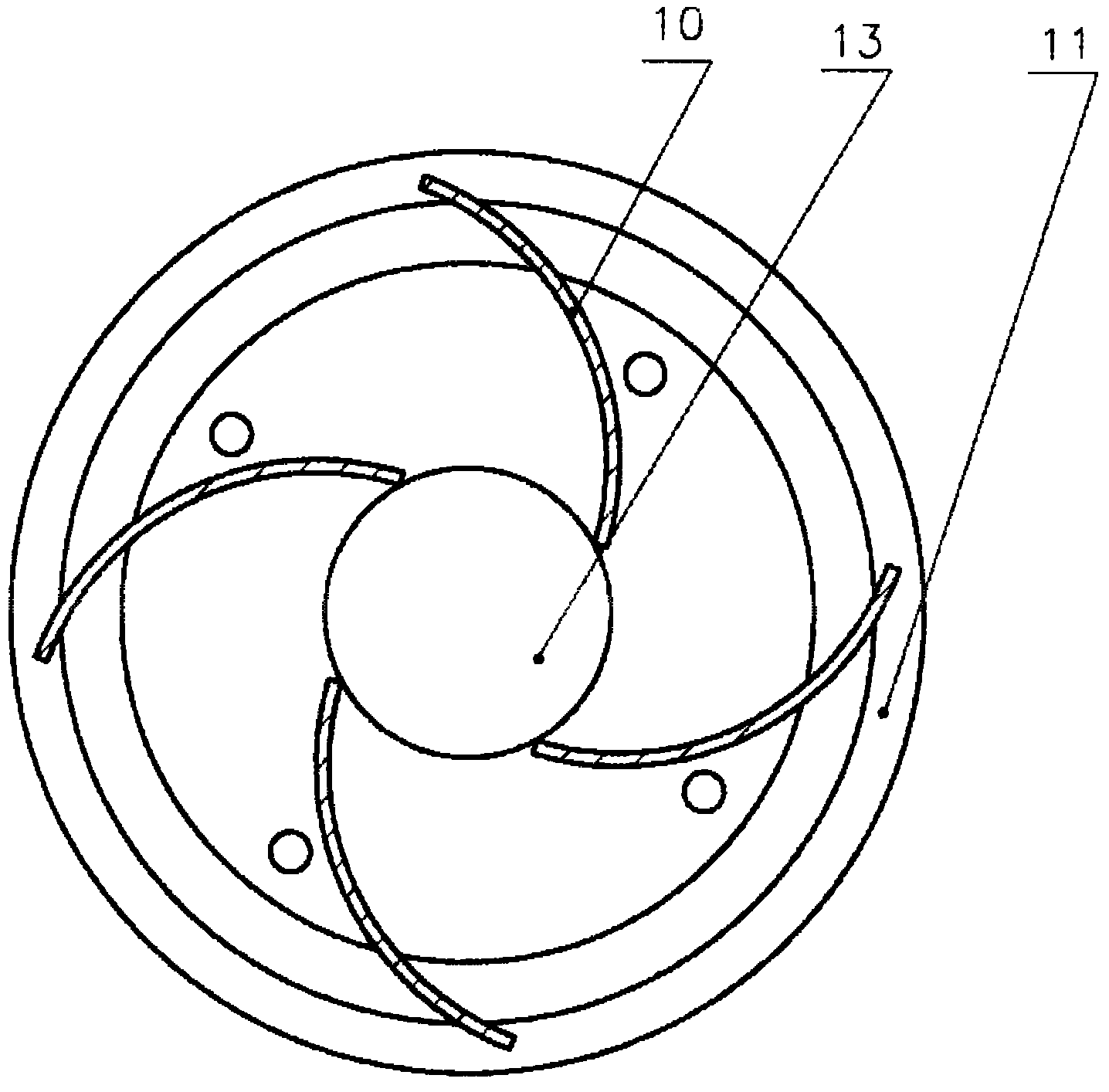
[0013] The bottom plate 11 of the cloth cone 14 is fixedly connected with the pusher plate 5 by welding with screws, and the pusher plate 5 is fixed to the support rod 6. The top plate 12 and the bottom plate 11 of the cloth cone 14 are equipped with four arc-shaped parabolic blades. 10; The upper and lower edges of the blade 10 are welded and fixed to the top plate 12 and the bottom plate 11, respectively. The top plate 12 and the bottom plate 11 are disc cones. There is a hole 13 in the middle of the cloth cone 14, and the cloth cone 14 has a top plate 12 and a bottom plate. 11 and the horn arc cavity 15 surrounded by the arc blades 10, the outlet end of the feed pipe 2 extends into the horn arc cavity from the hole 13, and the flushing pipe 1 is fixed on the centrifuge feeding pipe 2, and The pipes 2 are parallel, and the feed pipe 2 is fixed on the casing to maintain a static state...


PUM


Abstract

Disclosed is a distributing device of a piston-pusher centrifuge. Arc-shaped blades uniformly distributed are clamped and mounted between a top plate and a bottom plate, both the top plate and the bottom plate are in the shape of circular cones and form a distributing cone, a hole is reserved in the middle of the distributing cone, an outlet end of a feed pipe extends into the distributing cone, and an outlet end of a flushing pipe also extends into the distributing cone. The distributing device has the advantages of uniformity in distribution, low breakage rate and the like. Besides, even when viscosity of materials is high, concentration of suspension liquid is high, and particle size of the materials is small, the centrifuge can work normally, application range of the double-stage piston-pusher centrifuge can be widened while stability and reliability in use thereof can be improved, and stoppage for treating accumulated filter residues is omitted during running of the centrifuge. In addition, the distributing device in the technical scheme has the advantages of simple structure, convenience in manufacturing and maintenance, reliability in running and low overall price, and is suitable to be used with the double-stage piston-pusher centrifuge.

Description

Technical field [0001] The invention relates to a pusher centrifuge, in particular to a cloth device of a piston pusher centrifuge. Background technique [0002] The distributing device of the main components of the two-stage pusher centrifuge commonly used at present has the following disadvantages: 1. When the crushing rate of the separated material is strictly required, it will have a greater impact on the crushing rate and reduce the product quality; 2. The separated material is relatively viscous, the suspension concentration is too high, and the particle size of the material is too small, and the cloth will be uneven, which will cause the centrifuge to produce greater vibration, greatly reducing the stability and production capacity of the centrifuge; 3. When the particle size of the separated material Too small; accumulation formed between the pusher plate and the first-stage pusher drum, which will cause the centrifuge to be unbalanced and even damage the centrifuge. For ...

Claims


Application Information

Patent Timeline
Patent Type & Authority Applications(China)
IPC IPC(8): B04B11/00B04B15/12B04B3/02
CPCB04B3/02
Inventor 蒋立峰唐建清
Owner 蒋立峰
Why Eureka
Try Eureka