Discontinuous receiving method and equipment
A technology for discontinuous reception and user equipment, applied in the field of discontinuous reception methods and equipment, capable of solving problems such as large power consumption
- Summary
- Abstract
- Description
- Claims
- Application Information
AI Technical Summary
Problems solved by technology
Method used
Image
Examples
Embodiment 1
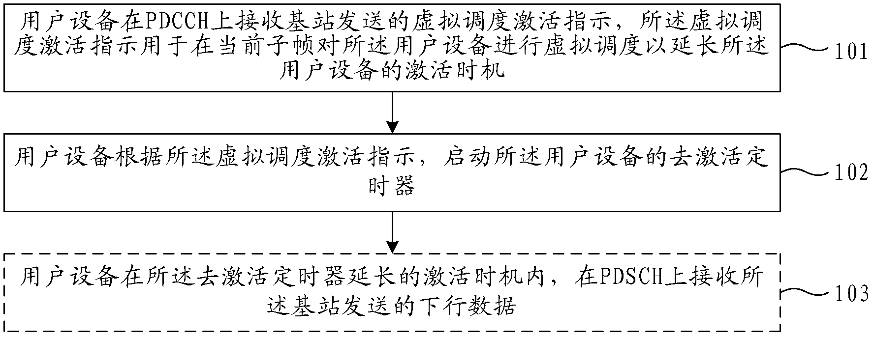
[0034] Figure 2a A flow chart of a discontinuous reception (DRX) method provided in Embodiment 1 of the present invention, such as Figure 2a As shown, the discontinuous reception method includes:
[0035] Step 101, the user equipment receives the virtual scheduling activation indication sent by the base station on the physical downlink control channel PDCCH, and the virtual scheduling activation indication is used to perform virtual scheduling on the user equipment in the current subframe to prolong the activation opportunity of the user equipment ;
[0036] In the embodiment of the present invention, when the virtual scheduling is performed on the user data in the current subframe, there is no actual data to be transmitted, and only the virtual scheduling is used to prolong the activation opportunity of the user equipment to detect the PDCCH.
[0037] Using step 101, if the activation opportunity of the user equipment conflicts with the special subframe of the base statio...
Embodiment 2
[0064] image 3 The flow chart of the discontinuous reception method provided by Embodiment 2 of the present invention, such as image 3 As shown, the discontinuous reception method includes:
[0065] Step 201, the base station sends a virtual scheduling activation indication to the user equipment on the physical downlink control channel PDCCH, and the virtual scheduling activation indication is used to perform virtual scheduling on the user equipment in the current subframe to extend the activation opportunity of the user equipment;
[0066] Before step 201, it may also include:
[0067] Configure the first code point value, the second code point value or the virtual wireless network temporary identifier; and / or,
[0068] Notifying the user equipment of the first code point value, the second code point value or the virtual wireless network temporary identifier through high layer signaling such as RRC signaling or MAC signaling.
[0069] Wherein, when there is downlink data...
Embodiment 3
[0078] Figure 4 A schematic structural diagram of the user equipment provided in Embodiment 3 of the present invention, as shown in Figure 4 As shown, the user equipment may include:
[0079] The receiver 41 is configured to receive a virtual scheduling activation indication sent by the base station on the physical downlink control channel PDCCH, where the virtual scheduling activation indication is used to perform virtual scheduling on the user equipment in the current subframe to extend the activation opportunity of the user equipment;
[0080] The deactivation timer 43 is configured to start when the receiver 41 receives the virtual scheduling activation indication, and the duration of the deactivation timer 43 includes an extended activation opportunity of the user equipment.
[0081] For the specific form of the virtual scheduling activation indication, refer to the relevant descriptions of the four examples in the first embodiment above.
[0082] In this embodiment, ...
PUM
 Abstract
Description
Claims
Application Information
 - R&D Engineer
- R&D Manager
- IP Professional
- Industry Leading Data Capabilities
- Powerful AI technology
- Patent DNA Extraction
Browse by: Latest US Patents, China's latest patents, Technical Efficacy Thesaurus, Application Domain, Technology Topic, Popular Technical Reports.
© 2024 PatSnap. All rights reserved.Legal|Privacy policy|Modern Slavery Act Transparency Statement|Sitemap|About US| Contact US: help@patsnap.com


