
Loop security automatic controlling system capable of resisting 30-degree angle error

A technology of automatic control system and differential loop, applied in the direction of information technology support system, power network operating system integration, circuit device, etc., can solve problems such as equipment damage, infeasibility, and reliability constraints of substation power supply, so as to achieve safe use, Improved power supply reliability and simple structure

Inactive Publication Date: 2012-12-26
ZAOZHUANG POWER SUPPLY COMPANY OF STATE GRID SHANDONG ELECTRIC POWER +1
View PDF5 Cites 2 Cited by
  • Summary
  • Abstract
  • Description
  • Claims
  • Application Information

AI Technical Summary

Problems solved by technology

[0003] However, the above method is not feasible for substations with a 30° phase angle difference between the main and backup power sources (such as 35kV substations)
Because if the main and backup power sources are connected through the busbar of the substation, a large circulating current will be generated, far exceeding the current-carrying limit of the power equipment (the circulating current is 4.7 times the rated current of the transformer), and it is very easy to cause damage to the equipment.
In order to avoid this situation caused by the wrong connection of the backup power switch, the backup power switch is generally in the cold standby state during operation. The function of being put into operation quickly requires operators to go to the site to perform switching operations, which takes a long time to restore power supply, and the reliability of power supply in substations is greatly restricted

Method used


Image

  • Loop security automatic controlling system capable of resisting 30-degree angle error
  • Loop security automatic controlling system capable of resisting 30-degree angle error

Examples


Embodiment Construction

[0012] The present invention will be further described below in conjunction with accompanying drawing and specific embodiment:

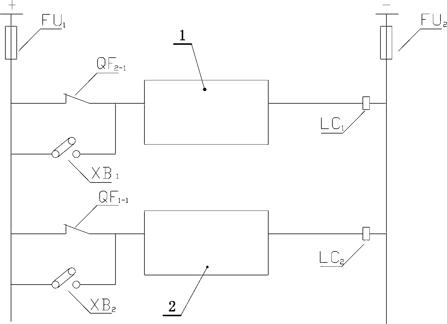
[0013] A loop safety automatic control system against 30° angle difference, such as figure 1 shown, the backup power switch auxiliary contact QF 2-1 , switch film XB 1 Parallel connection, and then with the main power supply closing control circuit, closing coil LC 1 Series connection; main power switch auxiliary contact QF 1-1 , switch film XB 2 Parallel connection, and then with the backup power supply closing control circuit, closing coil LC 2 Series connection; the DC power positive busbar is the same as the control power supply fuse FU 1 Connected in series, through the above two series circuits, and then through the control power supply fuse FU 2 , connected to the negative busbar of the DC power supply to form a closing circuit.

[0014] Under normal circumstances, the main power supply runs with a substation, and the auxiliary contact ...


PUM


Abstract

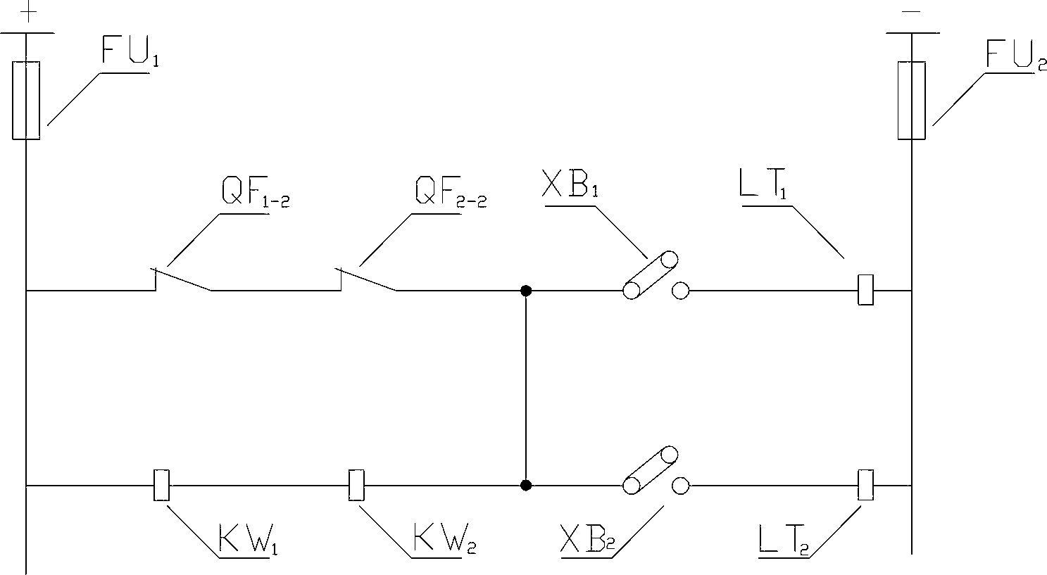
The invention discloses a loop security automatic controlling system capable of resisting a 30-degree angle error, wherein an auxiliary contact QF2-1and a switching sheet XB1 of a standby power supply switch are connected in parallel, and then are connected with a switching control loop and a switching coil LC1 of a main power supply in serial; an auxiliary contact QF-1 and a switching sheet XB2 of a main power supply switch are connected in parallel, and then are connected with a switching control loop and a switching coil LC2 of a standby power supply in serial; a positive bus of a DC (Direct Current) power supply is connected with a control power supply fuse FU1 in serial, passes through the previous two series circuits, and passes through a control power supply fuse FU2, and then is connected into a negative bus of the DC power supply, to form a switching loop; a main power supply breaker auxiliary contact QF1-2 and a standby power supply auxiliary contact QF2-2 are connected in serial and are connected with a circuit which is composed of a main power supply power direction relay KW1 and a standby power supply power direction relay KW2 which are connected in serial in parallel; the switching sheet XB1 is connected with a main power supply breaking coil LT1 in serial; and the switching sheet XB2 is connected with a standby power supply breaking coil LT2 in serial.

Description

technical field [0001] The invention relates to a safety automatic control device for an electric power system, in particular to a safety automatic control system for preventing a 30° angle difference loop. Background technique [0002] At present, the 35kV substation of the power system generally adopts the power supply mode of one master and one backup. Under normal circumstances, the substation is powered by the main power supply, and the backup power switch is in a hot standby state. When the main power supply in operation has a permanent failure, the substation quickly and automatically pulls the main power switch through the backup power automatic input device (referred to as standby self-switching), and closes the backup power switch to restore power to the substation. This mode of operation greatly improves the power supply reliability of the power system. [0003] However, the above method is not feasible for a substation (such as a 35kV substation) with a 30° pha...

Claims


Application Information

Patent Timeline
Patent Type & Authority Applications(China)
IPC IPC(8): H02J9/06
CPCY02B70/30Y04S20/20
Inventor 严洪君石磊王群孔令元揭一鸣廉震张友忠王祥军冯相军万卫东刘朋种法超聂坤凯
Owner ZAOZHUANG POWER SUPPLY COMPANY OF STATE GRID SHANDONG ELECTRIC POWER
Learn More