A power-based device temperature regulation method

A technology for temperature regulation and equipment, applied in mechanical equipment, pump control, non-variable pumps, etc., can solve the problem of high software overhead for timing polling, and achieve the effect of reducing software overhead and facilitating grouping

Inactive Publication Date: 2016-03-09
ZHEJIANG CHUANGYI PHOTOELECTRIC EQUIP
View PDF8 Cites 0 Cited by
  • Summary
  • Abstract
  • Description
  • Claims
  • Application Information

AI Technical Summary

Problems solved by technology

This requires that multiple temperature sensors need to be added to the single board during device design, and since the temperature sensor is a slow device, the software overhead required for regular polling is also relatively large

Method used


Image

  • A power-based device temperature regulation method
  • A power-based device temperature regulation method
  • A power-based device temperature regulation method

Examples


Embodiment Construction

[0012] The present invention will be further described below with reference to the accompanying drawings and specific embodiments.

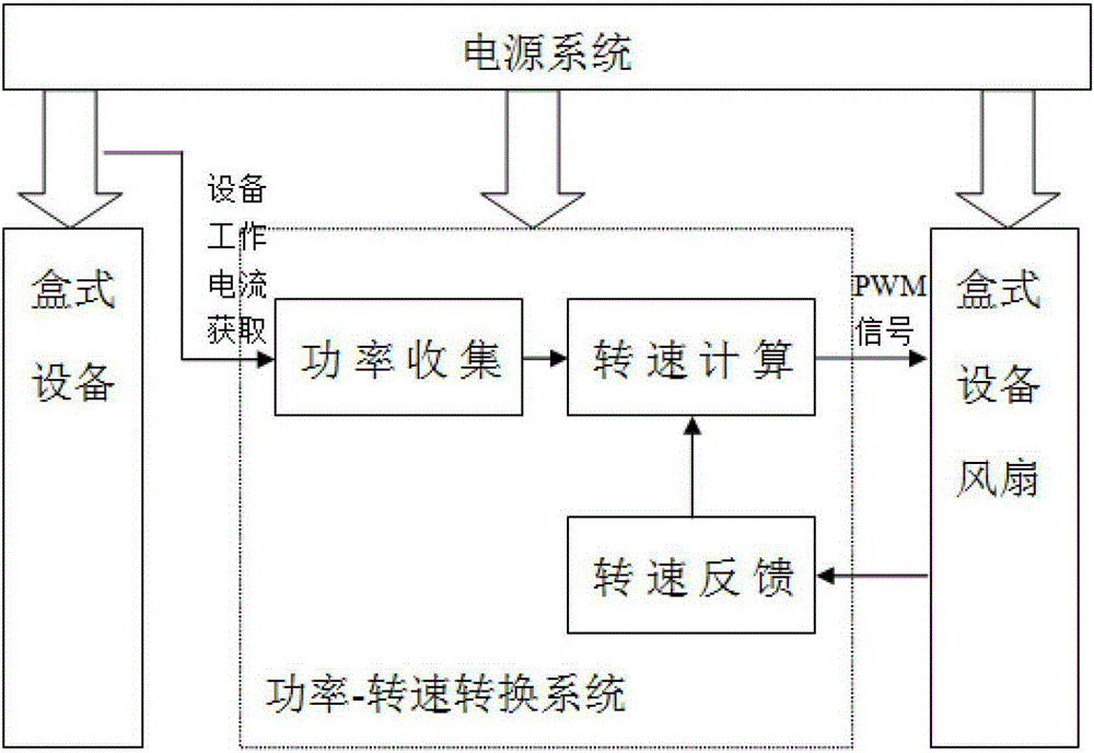
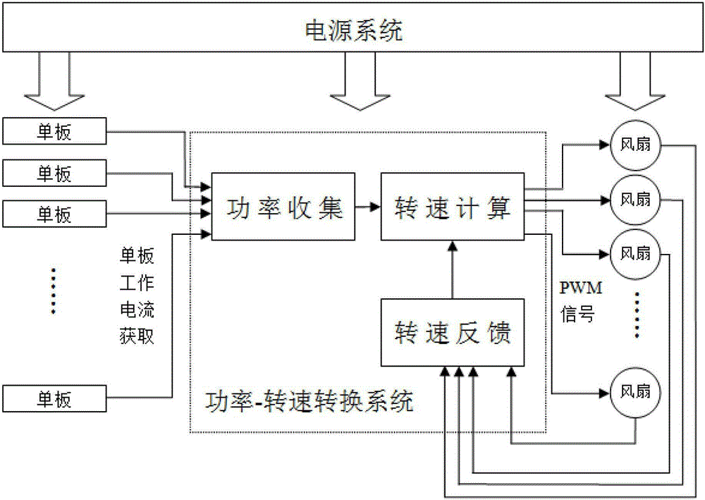
[0013] The present invention is a power-based device temperature adjustment method. Under the condition that the voltage of each circuit on the device is constant, the acquisition of power can be simplified as the acquisition of current.

[0014] The process that the present invention regulates the temperature of the equipment is as follows: figure 1 As shown in the figure, the current value of the board is obtained according to the hardware circuit, and the current value is converted into a PWM signal for adjusting the fan speed. The duty cycle of the PWM signal determines the fan speed. The larger the duty cycle, the higher the fan speed. If the current is greater than a certain value, set the PWM duty cycle to be the highest; if the current is less than a certain value, set the PWM duty cycle to be the lowest; if the current is between the min...


PUM


Abstract

The invention discloses a device temperature regulating method based on power. The device temperature regulating method comprises the following steps: acquiring current size, and converting the current value to a PWM (Pulse-Width Modulation) signal for regulating the rotation speed of fans; setting the duty cycle of the PWM signal to the highest when the current is bigger than the set maximum value; setting the duty cycle of the PWM signal to the lowest when the current is smaller than a set minimum value; converting the duty cycle of the PWM signal according to the size of the current value, controlling the rotation speed of the fans through the duty cycle of the PWM signal; directly controlling the rotation speed of the fans through hardware so as to reduce software overhead. When veneers are additionally arranged / reduced, or part of the fans are faulted / recovered, the rotation speed of the fans can be automatically adjusted correspondingly. The fans are conveniently grouped, so that the rotation speed is improved for the veneers with high heating efficiency, and reduced for a vacant slot or a veneer slot with a low heating efficiency, thereby achieving the greening and energy-saving purpose.

Description

technical field [0001] The present invention relates to a power-based device temperature adjustment method. Background technique [0002] Modern network communication equipment is developing in the direction of large-scale and high-density, and the port rate is moving from 10G to 40G / 100G. The rapid development of equipment performance has also brought about an increase in power consumption, which has brought higher requirements for equipment heat dissipation and energy saving. The current temperature adjustment of network equipment is generally an air-cooled design. The equipment usually has one or more fans (boxes), and the fan speed is adjusted through a PWM signal to achieve temperature control of the equipment. Therefore, the control of the device temperature is mainly the acquisition and setting of the fan speed. The fan speed is usually obtained based on the temperature of the device. That is, the software periodically polls the temperature-sensing temperature of ea...

Claims


Application Information

Patent Timeline
Patent Type & Authority Patents(China)
IPC IPC(8): F04D27/00
Inventor 高志寅
Owner ZHEJIANG CHUANGYI PHOTOELECTRIC EQUIP
Why Eureka
Try Eureka