Novel plunger pump device

A plunger pump, a new type of technology, is applied to the components of pumping devices for elastic fluids, pump elements, variable displacement pump components, etc. It can solve the problems of insufficient output pressure and low efficiency, and achieve large specific flow , high efficiency, simple and compact structure

Inactive Publication Date: 2012-12-26
ZHEJIANG UNIV
View PDF6 Cites 1 Cited by
  • Summary
  • Abstract
  • Description
  • Claims
  • Application Information

AI Technical Summary

Problems solved by technology

Although it can output high pressure when pumping medium with high viscosity, when the medium is water, gasoline and other liquids with low viscosity, the output pressure is not high enough due to leakage and other reasons, and the efficiency is relatively low

Method used


Image

  • Novel plunger pump device
  • Novel plunger pump device

Examples


Embodiment Construction

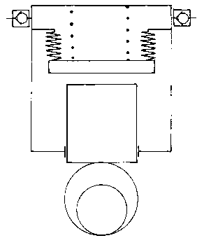
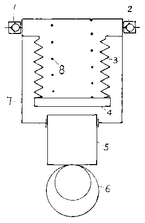
[0015] Such as figure 1 and 2 As shown, the novel plunger pump device of the present invention includes an input check valve 1, an output check valve 2, a folded spring spacer 3, a plate 4, a plunger 5, an eccentric shaft 6, a pump body 7 and a spring 8. The input one-way valve 1 and the output one-way valve 2 are fixed above the side wall of the pump body 7, the folded spring isolation ring 3 is placed in the pump body 7, the upper part is airtightly fixed on the inner wall of the pump body 7, and the lower part is airtightly connected to the flat plate 4, The folded spring isolation ring 3 and the flat plate 4 divide the pump cavity of the plunger pump into an inner cavity part and an outer cavity part; the outer cavity part is filled with oil whose viscosity coefficient is greater than water; the plunger 5 is placed on the column at the bottom of the pump body 7 In the plug hole, the eccentric shaft 6 is located below the plunger 5 and is in contact with the plunger 5. One...


PUM


Abstract

The invention discloses a novel plunger pump device. A ring of folding spring isolating rings and a flat plate are additionally arranged in a traditional plunger pump, so that the pump cavity of the plunger pump is divided into inner and outer parts; the inner cavity contains medium with low viscosity; and the outer cavity contains oil with high viscosity. The novel plunger pump device is big in output pressure, big in unit rate of flow, high in efficiency and small in size.

Description

technical field [0001] The invention relates to a novel plunger pump device, in particular to a radial plunger pump device for water or other low-viscosity media. Background technique [0002] The pump chambers of the existing radial piston pumps circulating on the market are all integrated. Although it can output high pressure when pumping medium with high viscosity, when the medium is water, gasoline and other liquids with low viscosity, the output pressure is not high enough due to leakage and other reasons, and the efficiency is relatively low. Contents of the invention [0003] The object of the present invention is to provide a novel radial piston pump device for the deficiencies of the prior art. When the medium is water, gasoline and other low-viscosity liquids, the invention can achieve high output pressure, high volumetric efficiency, large specific flow rate, small volume and simple structure. [0004] In order to achieve the above object, the technical scheme...

Claims


Application Information

Patent Timeline
Patent Type & Authority Applications(China)
IPC IPC(8): F04B53/00
Inventor 陈行
Owner ZHEJIANG UNIV
Why Eureka
Try Eureka