Endoscope system and poor visibility determination method
A technology of endoscope and field of view, which is applied in the field of endoscope system and can solve problems such as observation
- Summary
- Abstract
- Description
- Claims
- Application Information
AI Technical Summary
Problems solved by technology
Method used
Image
Examples
no. 1 Embodiment approach )
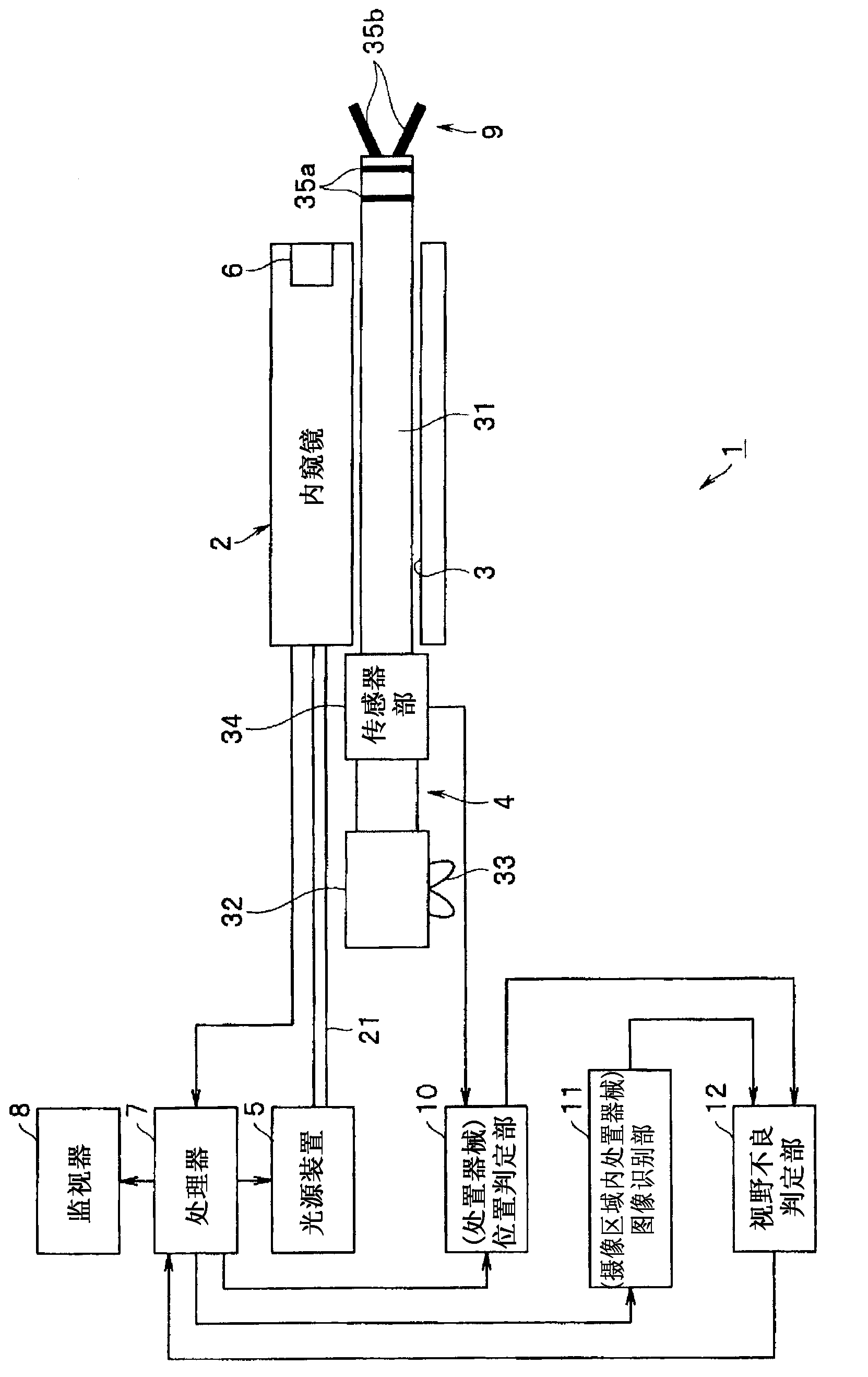
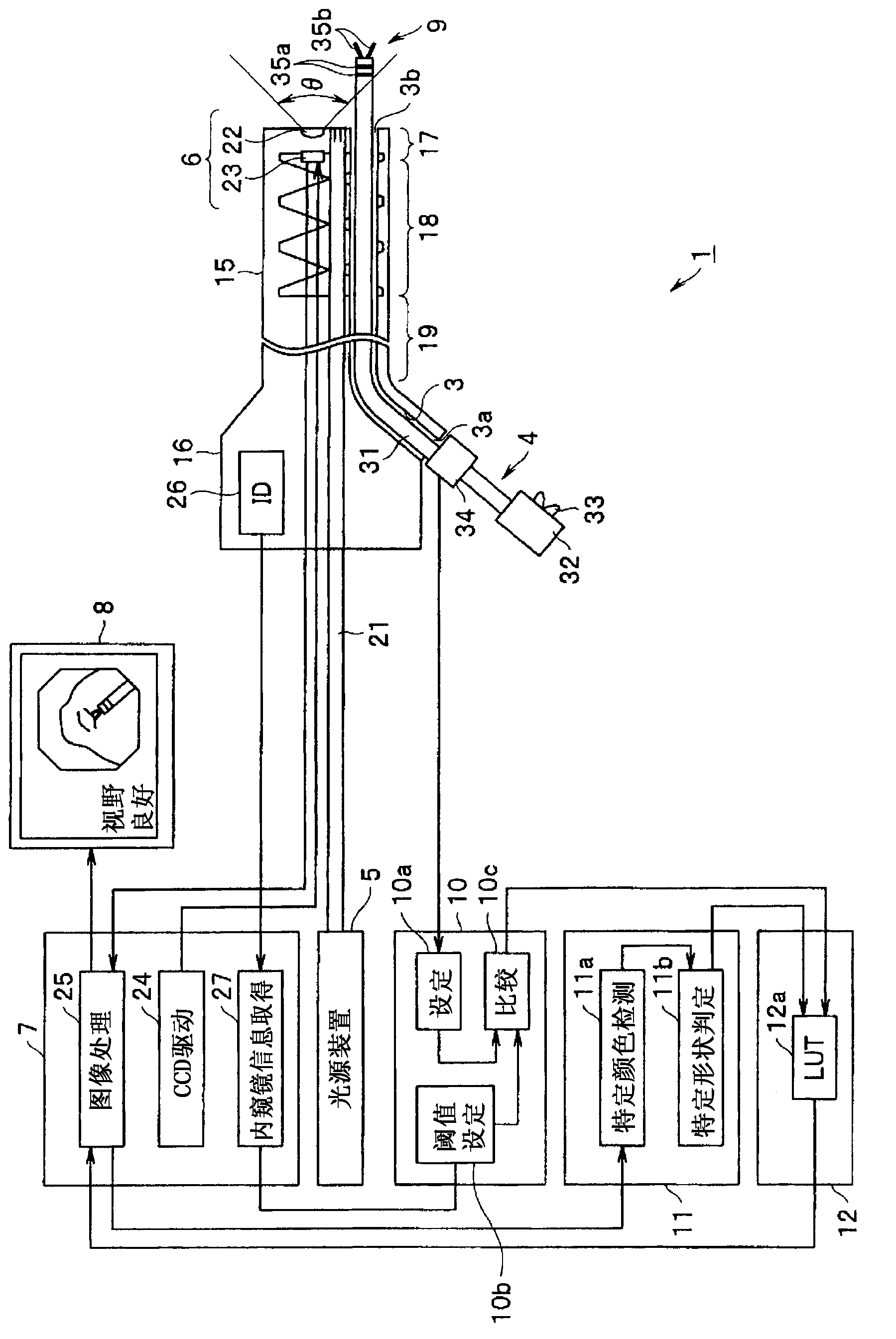
[0037] Such as figure 1 As shown, the endoscope system 1 according to the first embodiment of the present invention has an endoscope 2 inserted into the body, and a treatment instrument inserted into a treatment instrument channel (abbreviated as channel) 3 of the endoscope 2 . 4. and a light source device 5 for supplying illumination light to the endoscope 2 .
[0038] Furthermore, this endoscope system 1 has: a processor 7 as a signal processing unit that performs signal processing on an imaging unit 6 as an imaging unit provided in the endoscope 2; and a monitor 8 as a display unit that performs signal processing. An endoscopic image corresponding to the image signal generated by the processor 7 is displayed.
[0039] In addition, the light source device 5 and the processor 7 may be connected by a signal line, and the light quantity of the illumination light of the light source device 5 may be adjusted based on the brightness signal of the image signal from the processor 7...
no. 2 Embodiment approach )
[0102] Next, refer to Figure 5 to Figure 9 A second embodiment of the present invention will be described. Figure 5 The overall configuration of an endoscope system 1B according to the second embodiment of the present invention is shown.
[0103] Figure 5 The endoscope system 1B is shown in figure 1 In the endoscope system 1 of , instead of the treatment instrument 4, a high-frequency treatment instrument 4B for performing treatment using high-frequency electric energy is used, and the high-frequency treatment instrument 4B is connected to a high-frequency power supply device 41 as a power supply device.
[0104] Furthermore, this high-frequency power supply device 41 is connected to a foot switch ( Figure 5 Abbreviated as FS) 42 connections. The high-frequency cauterization device 43 is formed by the high-frequency treatment instrument 4B, the high-frequency power supply device 41 and the foot switch 42 .
[0105] For example, like the first embodiment, this high-fre...
no. 3 Embodiment approach )
[0165] Next, refer to Figure 10 ~ Figure 12 A third embodiment of the present invention will be described. Figure 10 The overall configuration of an endoscope system 1C according to a third embodiment of the present invention is shown.
[0166] Endoscopy System 1C in Figure 5 In the endoscope system 1B of the second embodiment shown, instead of the manual high-frequency treatment instrument 4B, an active high-frequency treatment instrument (abbreviated as high frequency disposal equipment) 4C. Furthermore, the high-frequency cauterization device 43C is formed by the high-frequency treatment instrument 4C, the high-frequency power supply device 41 and the foot switch 42 .
[0167] In addition, the endoscope system 1C of the present embodiment has a control unit 51 that controls the operation of the high-frequency treatment instrument 4C and controls the energy supply operation of the high-frequency power supply device 41 as the energy supply device. control. The control...
PUM
 Abstract
Description
Claims
Application Information
 - R&D
- Intellectual Property
- Life Sciences
- Materials
- Tech Scout
- Unparalleled Data Quality
- Higher Quality Content
- 60% Fewer Hallucinations
Browse by: Latest US Patents, China's latest patents, Technical Efficacy Thesaurus, Application Domain, Technology Topic, Popular Technical Reports.
© 2025 PatSnap. All rights reserved.Legal|Privacy policy|Modern Slavery Act Transparency Statement|Sitemap|About US| Contact US: help@patsnap.com


