
an axial fan

A technology for axial flow fans and blades, applied in the field of axial flow fans, which can solve the problems of increased fan noise, affecting the performance of axial flow fans, noise, etc.

Active Publication Date: 2015-12-16
GREE ELECTRIC APPLIANCES INC
View PDF9 Cites 0 Cited by
  • Summary
  • Abstract
  • Description
  • Claims
  • Application Information

AI Technical Summary

Problems solved by technology

[0003] When the hub of the existing axial flow fan rotates, the blades of the axial flow wind wheel will produce relatively strong trembling vibration with the rotation of the hub, causing the vibration of the entire axial flow fan, which in turn leads to strong vibration of the whole machine, resulting in greater noise impact
At the same time, the existing axial flow fan blades are relatively flat. When the axial flow rotates, a large pressure difference will be generated between the pressure surface and the suction surface of the blade. The backflow of the suction surface in the state will cause gas turbulence, separation of the boundary layer and vortex phenomenon, which will increase the noise of the fan and affect the performance and service life of the whole machine.
[0004] It can be seen that the existing axial flow fan will generate relatively large noise due to blade tremor and blade vortex phenomenon, which will affect the performance of the axial flow fan. Therefore, how to solve the noise problem caused by blade tremor and vortex phenomenon during the rotation of the axial flow fan It is a technical problem that those skilled in the art urgently need to solve

Method used

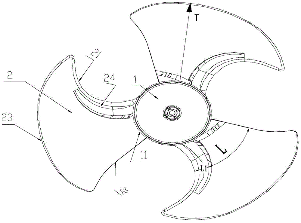
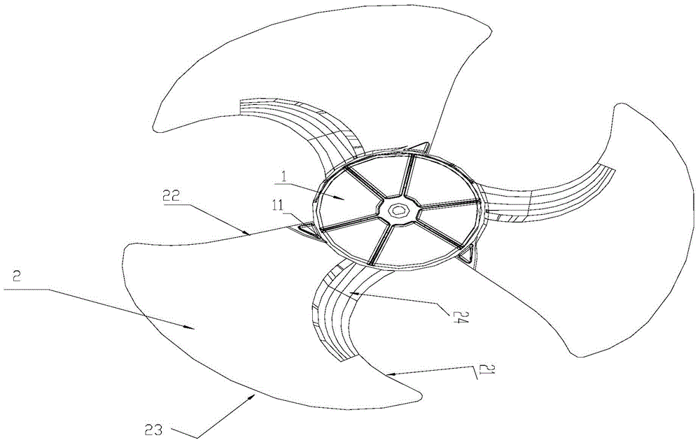
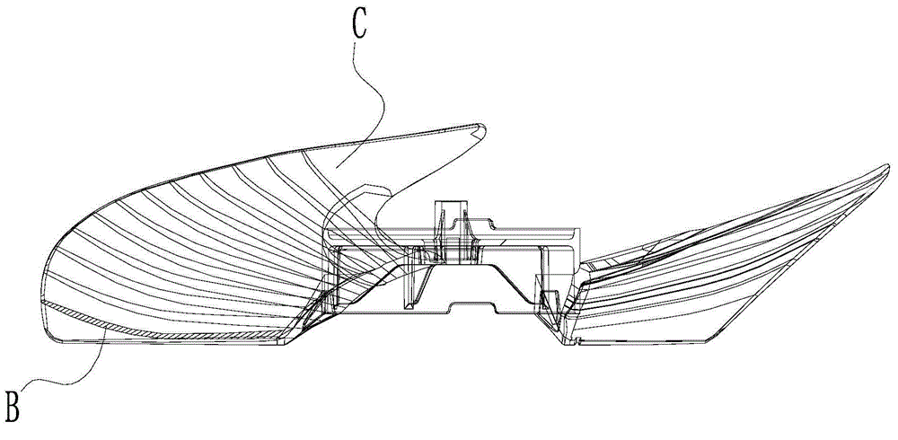

Image

  • an axial fan
  • an axial fan
  • an axial fan

Examples


Embodiment Construction

[0086] The following will clearly and completely describe the technical solutions in the embodiments of the present invention with reference to the accompanying drawings in the embodiments of the present invention. Obviously, the described embodiments are only some of the embodiments of the present invention, not all of them. Based on the embodiments of the present invention, all other embodiments obtained by persons of ordinary skill in the art without making creative efforts belong to the protection scope of the present invention.

[0087] The two sides of each blade of the axial flow fan along the axial flow direction are the pressure surface and the suction surface respectively, the edge of each blade on the same side as its rotation direction is the leading edge, and the edge on the opposite side of the rotation direction is the trailing edge. The radially outward edge is the outer edge. When the existing axial flow fan rotates, due to blade vibration or eddy current pheno...


PUM


Abstract

The invention discloses an axial fan, comprising a hub and a plurality of blades arranged on the periphery of the hub. Leading edges of the blades are provided with thickened sections, the thickened sections extend from the root of the hub to outer edges of the blades, and extend by a set length from the leading edges of the blades to the rear edges of the blades along an equal-primitive arc; and the blades bend to a suction surface or a pressure surface, so the suction surface or the pressure surface is enabled to form a curved surface. During the movement of the axial fan, the shudder and the eddy current phenomenon of the blades are reduced, the noise produced by the axial fan is decreased, and the overall performance of the axial fan is improved.

Description

technical field [0001] The invention relates to the technical field of axial flow wind wheels, and more specifically relates to an axial flow fan. Background technique [0002] Axial flow fans are widely used as air supply components in air conditioner outdoor units and some ventilation equipment. An axial flow fan includes a hub and several blades arranged on the hub, and the design of the blades directly affects the overall performance of the outdoor air conditioner and air supply equipment. [0003] When the hub of the existing axial flow fan rotates, the blades of the axial flow wind wheel will produce relatively strong trembling vibration with the rotation of the hub, causing the vibration of the entire axial flow fan, which in turn leads to strong vibration of the whole machine, resulting in greater noise impact . At the same time, the existing axial flow fan blades are relatively flat. When the axial flow rotates, a large pressure difference will be generated betwee...

Claims


Application Information

Patent Timeline
Patent Type & Authority Patents(China)
IPC IPC(8): F04D29/38
Inventor 刘中杰龙斌华刘利娜曹锋
Owner GREE ELECTRIC APPLIANCES INC
Learn More