A hub clamp

A fixture and hub technology, which is applied in the field of automated tooling and fixtures, can solve the problems of inability to grip special-shaped workpieces, single fixture functions, and easy damage to workpieces.

Active Publication Date: 2016-12-21
SHANGHAI SONGSHENG ROBOT SYST CO LTD
View PDF8 Cites 0 Cited by
  • Summary
  • Abstract
  • Description
  • Claims
  • Application Information

AI Technical Summary

Problems solved by technology

[0003] The existing fixture has a single function and poor overall flexibility. It cannot clamp some special-shaped workpieces and is easy to damage the workpiece. Therefore, it is still necessary to further improve the existing automatic fixture structure and further improve its overall performance.

Method used


Image

  • A hub clamp
  • A hub clamp
  • A hub clamp

Examples


Embodiment Construction

[0011] The present invention will be further described below with reference to the accompanying drawings.

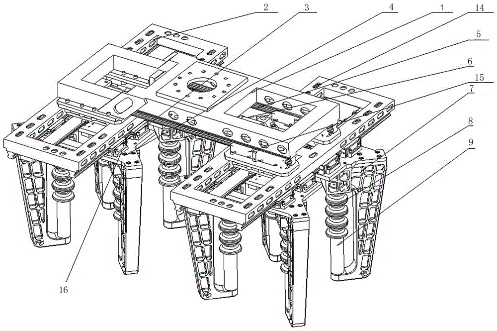
[0012] The present invention is a hub clamp, which includes a main beam 1, which is different from the prior art in that: both sides of the main beam 1 are provided with a sub-beam moving guide rail 5, and the two ends of the main beam 1 are respectively provided with first auxiliary beams. The beam 2 and the second sub-beam 14, the upper surface of the first sub-beam 2 and the second sub-beam 14 are provided with a sub-beam guide rail slider 15, and the first sub-beam 2 and the second sub-beam 14 slide through the sub-beam guide rail The block 15 is movably connected with the sub-beam moving guide rail 5, and the two sides of the lower surface of the first sub-beam 2 and the second sub-beam 14 are respectively provided with a clamping arm moving sub-guide rail 3, and the clamping unit is connected with the clamping unit slide block 16. The clamping arm moves the auxilia...


PUM


Abstract

The invention discloses a hub fixture. The hub fixture comprises a main beam, wherein two sides of the main beam are respectively provided with an auxiliary beam moving guide rail, two ends of the main beam are respectively provided with an auxiliary beam, auxiliary beam guide rail sliding blocks are arranged on the upper surfaces of the auxiliary beams, the auxiliary beams are movably connected through the auxiliary guide rail sliding blocks and the auxiliary beam moving guide rails, and two sides of the lower surface of each auxiliary beam are respectively provided with a clamping arm moving auxiliary guide rail. According to the hub fixture disclosed by the invention, a non-metal cylindrical clamping post and a clamping wheel are adopted, the position variation of a non-metal clamping unit is realized by matching with a multi-layer vertical translation guide rail frame, the whole design mechanism of the hub fixture is reasonable, the design is ingenious, the working state is stable, the loss of workpiece can be avoided due to the non-metal flexible cylindrical clamping post and the clamping wheel, and the hub fixture can be applied to the grab of various different workpiece and is beneficial to be popularized and applied.

Description

technical field [0001] The invention relates to the technical field of automatic tooling fixtures, in particular to a hub-type fixture, and in particular to its mechanical connection structure. Background technique [0002] Comparative document 1, patent number: CN201120413438.4, application date: 2011.10.26, patentee: Guiyang Aluminum Magnesium Design and Research Institute Co., Ltd., this case discloses "an automatic fixture capable of lifting cylindrical electrodes", including the ability to burn deeply The guide frame in the tank is characterized in that: the guide frame is fixedly connected with a fixed support, and the fixed support is hinged with the left and right clamp arms through the hinge axis a and the hinge axis b, and the support rod is connected through the hinge axis c and The hinge axis d is hingedly connected with the left clamp arm and the right clamp arm, the connecting rod a and the connecting rod b are hingedly connected with the right clamp arm throug...

Claims


Application Information

Patent Timeline
Patent Type & Authority Patents(China)
IPC IPC(8): B25J15/00B25J11/00
Inventor 马立祥
Owner SHANGHAI SONGSHENG ROBOT SYST CO LTD
Why Eureka
Try Eureka