
Design method of film, television and stage lamp power supply system

A technology for power supply system and stage lighting, which is applied in electric light circuit arrangement, light source, electric light source, etc. It can solve the problems of insufficient circuit power, excess number of circuits, waste of cables, etc., so as to reduce the difficulty of installation and design and improve the utilization rate of equipment. , the effect of improving flexibility

Active Publication Date: 2012-12-12
GUANGZHOU LEAFUN CULTURE SCI & TECH
View PDF4 Cites 20 Cited by
  • Summary
  • Abstract
  • Description
  • Claims
  • Application Information

AI Technical Summary

Problems solved by technology

Therefore, the preset point cannot cover the actual application point, and cannot meet the actual circuit specification and property requirements, resulting in a series of problems:
Since the position of each circuit in the power supply system has been fixed, but the actual layout of the lighting position is flexible and changeable, this leads to: On the one hand, the position of the circuit in the power supply system cannot fully cover the actual circuit position, resulting in some locations that need electricity without electricity. , but some places that do not need electricity have the embarrassing situation of electricity, so that the number of circuits is relatively insufficient in actual use; on the other hand, not every performance needs to use all or most of the power supply system circuits. The number only accounts for 10%~20% of the total number of circuits in the power supply system, and the number of circuits is absolutely excessive, resulting in waste of cables and equipment resources
[0009] (2) The number of loops of various properties is relatively insufficient and absolute excess
Since the nature of each circuit in the power supply system (dimming or through) has been determined in advance, there may be situations where the number of dimming circuits (or through circuits) in the system does not match the number of dimming circuits (or through circuits) actually required, for example The number of dimming circuits preset by the system is less than the number of dimming circuits actually needed, or the number of straight-through circuits preset by the system is more than the number of straight-through circuits actually needed, resulting in insufficient or excess number of circuits of various properties
[0010] (3) Uncertainty in the nature of the loop
Due to a large number of automated lamps and new light source lamps being introduced into use, whether the nature of the loop is dimming or straight-through, there are many changes in use and cannot be determined, causing many contradictions and accidents
[0011] (4) Possibly insufficient loop power and absolute waste
Since the power of each loop of the power supply system has been determined, but in actual use, the power of each loop of the power supply system cannot fully cover the actual power of the lamp, and often encounter situations where the actual required power does not match the set power of the loop. If the required power is greater than the set power of the loop, the loop power will be relatively insufficient; if the actual required power is less than the set power of the loop, part of the loop power will be wasted
In actual use, the power of most lamps used in each performance is far lower than the power of the installation circuit, resulting in waste of resources
[0012] (5) Three-phase unbalance
[0013] (6) The structure of the power supply system is unreasonable and there are potential safety hazards
Unbalanced three phases and changes in power consumption cause major fire hazards in the silicon control room and the main trunking area
On the other hand, the number, location, specifications and nature of the circuits of the existing professional lighting power supply system have been installed and fixed in advance. Specifications, there may also be conflicts between temporary cables and movable mechanisms, resulting in new safety hazards
[0014] (7) Waste of resources and serious interference
As mentioned in points (1) to (4) above, the number, location, specifications and nature of the circuits of the existing professional lighting power supply system have been installed and fixed in advance, and it is impossible to use them according to various types and scales afterwards. Or scene adjustments, use requirements are not met or some resources are not used, resulting in a lot of waste of resources, such as a lot of waste of cables (large-scale theater lighting cables use more than 25 tons of copper), and these large numbers of cables, interference range Large, takes up a lot of space (the specification of the lighting main trunking exceeds 1200*300, 2 pieces), and the installation workload is large (more than 90% of the workload of the stage lighting project is on the laying of cables)
[0015] All in all, because the existing professional lighting power supply system adopts the loop power supply method, the number, location, specification and nature of each power consumption circuit have been installed and fixed in advance, and it is impossible to make reasonable system adjustments according to the actual situation in actual use, resulting in The above-mentioned problems such as inconvenient use, heavy installation workload, serious waste of resources, and violation of electricity safety regulations have hindered the development and application of stage lighting.

Method used


Image

  • Design method of film, television and stage lamp power supply system
  • Design method of film, television and stage lamp power supply system
  • Design method of film, television and stage lamp power supply system

Examples


Embodiment Construction

[0047] The present invention will be further described below in conjunction with drawings and embodiments.

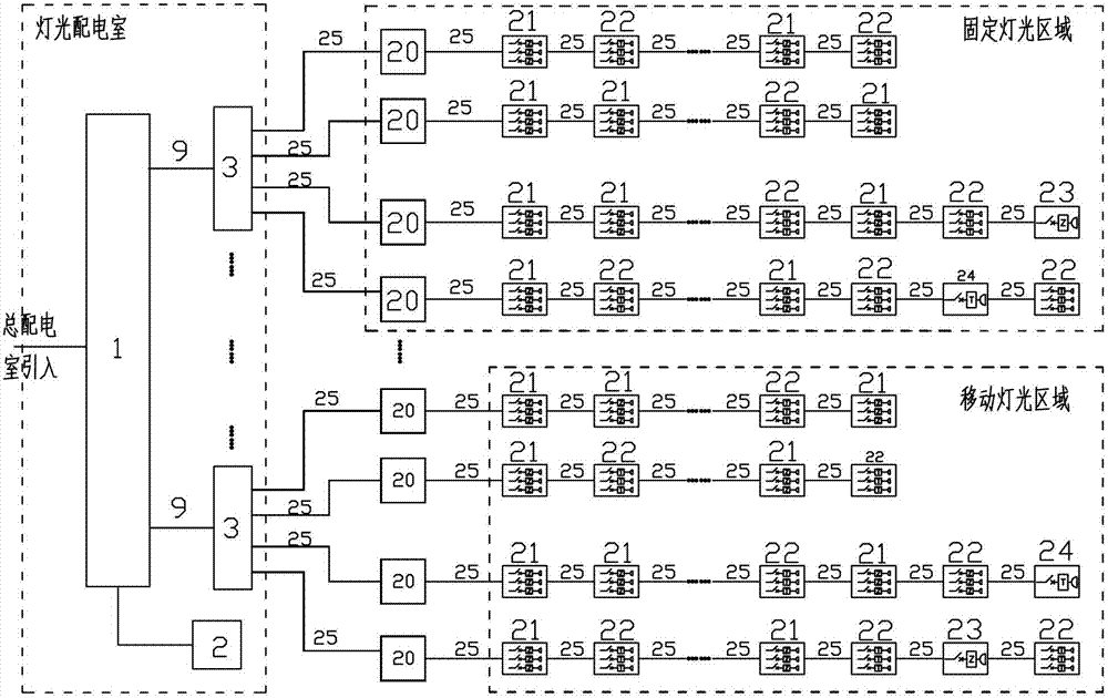
[0048] Such as figure 2 As shown, the film and television and stage lighting power supply system of this embodiment includes: a power distribution system and several regional distribution boxes 20, the power distribution system is used to receive external power and distribute it to each regional distribution box 20, the region The distribution box 20 is used to provide power for electrical equipment (especially lighting equipment) in a predetermined power supply area. Each area distribution box 20 is connected to one or more groups of socket modules, and each group of socket modules includes one or more series The socket modules in the same group are not limited to be connected in series or in parallel. The specific connection method needs to be determined according to the actual power consumption situation, such as power consumption location and power consumption. Th...


PUM


Abstract

The invention relates to a design method of a power supply system, in particular to a design method of a film, television and stage lamp power supply system. The design method comprises the following steps: step S10), dividing a light-required position of a light system into a plurality of power supply regions, and configurating regional distribution boxes with corresponding power; step S20), determining the standard of multi-core cables according to the regional distribution box with the maximum power supply power; step S30), determining the quantity, the power and the positions of socket modules connected with all the connection socket modules of each regional distribution box according to the utmost possible light quantity and the light power of each power supply region; and step S40), determining whether the socket modules are direct current socket modules or dimming socket modules according to the properties of the lights connected with the socket modules. The design mode breaks the limitation of the traditional thinking and can enable staff to adjust the quantity, the power and the positions of the lights according to the actual requirements in the mode of dispersing the regional power supply, so that the flexibility of the design and the installation of a light system can be greatly enhanced, and the project cost and the installation difficulty can be reduced.

Description

technical field [0001] The invention relates to a power supply system, in particular to a design method for a lighting power supply system suitable for professional lighting occasions such as film and television, theaters, and stages. Background technique [0002] Based on the requirements of artistic effects, professional lighting systems such as film and television, theaters, and stages usually need to adjust some or even all of the lights. The power supply system of these professional lighting systems generally uses dimming cabinets for centralized dimming and power supply control. For example, for large-scale theaters (or studios), the number of dimming and through circuits can reach hundreds or even thousands of circuits. The power distribution equipment and dimming equipment (dimming cabinets) of these circuits are all installed in one Specially set room - silicon control room. The power supply department transmits all the electricity to the silicon control room, whe...

Claims


Application Information

Patent Timeline
IPC IPC(8): H05B37/02
Inventor 杨华祥
Owner GUANGZHOU LEAFUN CULTURE SCI & TECH
Learn More