
Splashing preventing and oily water collecting device for pressure cooker

A collection device, pressure cooker technology, applied in pressure cooker, overflow prevention, cooking utensils and other directions, can solve the problems of difficult popularization and application, implementation restrictions, easy to disturb people, etc.

Inactive Publication Date: 2012-12-12
戴永锋
View PDF10 Cites 0 Cited by
  • Summary
  • Abstract
  • Description
  • Claims
  • Application Information

AI Technical Summary

Problems solved by technology

When the pressure cooker is exhausting under pressure limitation, most of the gas discharged is from the horizontally arranged exhaust holes (usually four, hereinafter referred to as: cap hole), this pressure-limited exhaust state makes the pressure cooker prone to the following deficiencies during the cooking process: (1). The hot gas mixed with oil, water and fine food particles ejected along the horizontal direction (hereinafter collectively referred to as: mixed fluid ) is easy to directly splash on the utensils around the pressure cooker and affect its hygienic state; (2). It is inconvenient; (3). The mixed fluid with a longer range is easy to spread in a farther or larger space, which is not conducive to the suction and timely discharge of the range hood; (4). The noise generated by the sprayed mixed fluid large and disturbing
The technical solution provided by the latter document sprays the oil and water gathered around the bonnet through the air duct connected to the upper part of the muffler cover, which makes it easier to increase the limited pressure exhaust pressure in the pressure cooker, especially when there is an abnormality that the air duct is blocked state, will significantly increase the gas pressure in the pressure cooker, and bring safety hazards to the use of the pressure cooker, so that the implementation of this technical solution is greatly restricted
[0006] In a word, the prior art is not easy to popularize and apply because of the use defects or potential use safety problems, so that the existing pressure cooker is prone to problems in the cooking process. could not be properly and effectively resolved

Method used


Image

  • Splashing preventing and oily water collecting device for pressure cooker
  • Splashing preventing and oily water collecting device for pressure cooker
  • Splashing preventing and oily water collecting device for pressure cooker

Examples


Embodiment 1

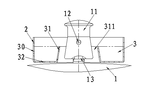
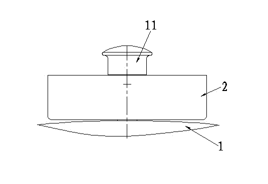
[0026] The anti-splash and oil-water collection device of the cooking pressure cooker according to Embodiment 1 of the present invention (for the structure see figure 1 , figure 2 and Figure 9 ), including a cylinder cover 2 located on the lid 1 of the pressure cooker around the pressure limiting valve to block the mixed fluid sprayed from the pressure limiting valve, and its structural characteristics are:

[0027] The lower part of the cylinder cover 2 is provided with an annular groove-shaped receiving groove 3 on the pot cover 1 surrounding the pressure limiting valve bonnet 11;

[0028] The above-mentioned receiving groove 3 is connected between the outer ring wall 30 integrated with the tube cover 2 and the cylindrical inner ring wall 31 with a through hole 311 located at the inner periphery of the tube cover 2 and integrally connected between the bottom ends of the two. The circular groove bottom 32 encloses and forms;

[0029]The above-mentioned through hole 311 a...

Embodiment 2

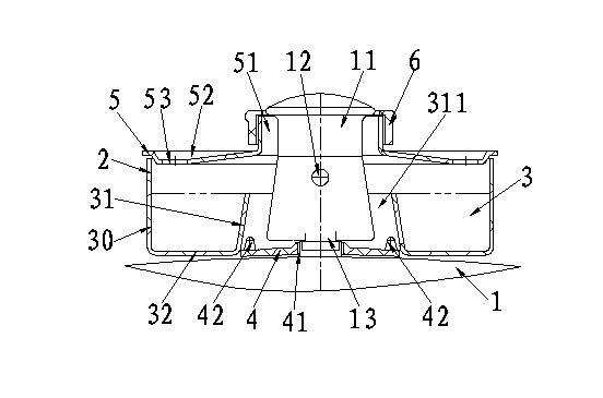
[0039] The anti-splash and oil-water collection device of the cooking pressure cooker according to the second embodiment of the present invention (for the structure see Figure 3 to Figure 5 , Figure 9 and Figure 10 ). On the basis of Embodiment 1 of the present invention, in order to make the function of the device of the present invention more perfect, so as to make it easier to implement and apply, the following structure is further constructed, and its benefits are also described later.

[0040] Further structure 1: On the pot cover 1 located on the inner periphery of the inner ring wall 31 and below the valve cap 11, a sleeve shoulder 4 surrounding the pressure limiting valve is provided; the sleeve shoulder 4 is connected to the sleeve seat 13 through the sleeve hole 41 There is a suitable gap between the sleeve shoulder 4 and the bottom end side of the bonnet 11 for the passage of the mixed fluid; The gap between the sides is uniform and stable. This provides a re...

Embodiment 3

[0050] The anti-splash and oil-water collection device of the cooking pressure cooker according to the third embodiment of the present invention (for the structure see Figure 6 to Figure 10). On the basis of the second embodiment of the present invention, the third embodiment is further configured as follows.

[0051] Above-mentioned cover shoulder 4 is provided with the recessed notch 43 that is positioned at the mouth portion outwards between two adjacent protruding heads 42; The sleeve fork 44 that shoulder 4 is integrally connected, the sleeve fork 44 is positioned at the lower side portion of tank bottom 32 and has suitable height, so that there is suitable space between the lower side of tank bottom 32 and the surface of pot cover 1 to supply oil and water. circulation gap.

[0052] The notch 43 and the gap between the groove bottom 32 and the pot cover 1 provided in this embodiment have the following functions in cooperation: (1). When the pressure cooker using the d...


PUM


Abstract

The invention provides a splashing preventing and oily water collecting device for a pressure cooker. The splashing preventing and oily water collecting device comprises a barrel cover 2, an annular receiving groove 3 which surrounds a pressure limiting valve by a circle is arranged on the lower portion of the barrel cover 2, and consists of an outer ring wall 30, an inner ring wall 31 and a groove bottom 32, and the groove bottom 32 is integrally connected with the bottom ends of the outer ring wall 30 and the inner ring wall 31; the inner ring wall 31 is positioned on the inner periphery of the barrel cover 2 and is provided with a through hole 311; a valve bonnet 11 can penetrate through the through hole 311, and a proper gap is reserved between the through hole 311 and the valve bonnet 11; the peripheral edge of the upper end of the inner ring wall 31 and the peripheral edge of the upper end of the through hole 311 are not higher than the lower edge of a bonnet hole 12; and the receiving groove 3 can receive oily water dripped from the inner wall of the barrel cover 2 and has preset volume. The splashing preventing and oily water collecting device has functions of preventing splashing, collecting the oily water and reducing noise, does not affect safety use of the pressure cooker, is simple in structure, can be sleeved on the existing pressure cooker at any time during use, brings convenience for cooking, and is easy to popularize and apply.

Description

technical field [0001] The invention relates to an anti-splash and oil-water collection device for a cooking pressure cooker. Background technique [0002] The cooking pressure cooker (hereinafter referred to as: pressure cooker) that the public uses on the gas range or induction cooker daily, for safety needs, the pot cover of pressure cooker is provided with gravity-type pressure-limiting exhaust valve (hereinafter referred to as: pressure-limiting valve). When the pressure cooker is exhausting under pressure limitation, most of the gas discharged is from the horizontally arranged exhaust holes (usually four, hereinafter referred to as: cap hole), this pressure-limited exhaust state makes the pressure cooker prone to the following deficiencies during the cooking process: (1). The hot gas mixed with oil, water and fine food particles ejected along the horizontal direction (hereinafter collectively referred to as: mixed fluid ) is easy to directly splash on the utensils aro...

Claims


Application Information

Patent Timeline
Patent Type & Authority Applications(China)
IPC IPC(8): A47J27/08A47J36/00
CPCA47J27/08A47J27/09A47J27/58
Inventor 戴永锋黄昊戴梦云
Owner 戴永锋
Learn More