Arrangement For Cutting Nail Blanks From An Intermittently Fed Wire

A wire and distribution technology, which is applied to the device for shearing and forming blanks, shearing devices, nails, etc., can solve the problems of high mechanical cost and large overall size of the device, and achieve the effect of flexible use and reduced complexity.

Inactive Publication Date: 2012-12-05
WAFIOS AKTIENGES
View PDF15 Cites 1 Cited by
  • Summary
  • Abstract
  • Description
  • Claims
  • Application Information

AI Technical Summary

Problems solved by technology

In general, it follows from this that the cutting of the dispensing device requires a ver

Method used


Image

  • Arrangement For Cutting Nail Blanks From An Intermittently Fed Wire
  • Arrangement For Cutting Nail Blanks From An Intermittently Fed Wire
  • Arrangement For Cutting Nail Blanks From An Intermittently Fed Wire

Examples


Embodiment Construction

[0025] In the following description of the figures, corresponding parts are always given the same references in the different exemplary embodiments.

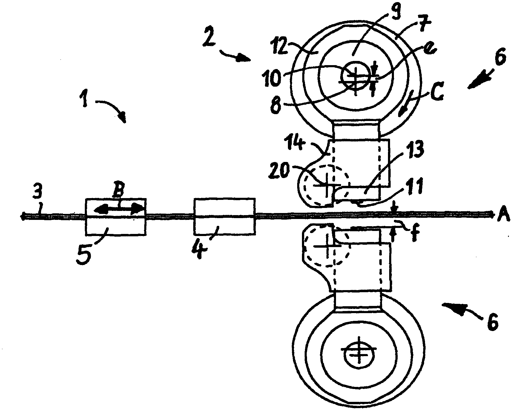
[0026] figure 1 The shown distributing device for cutting nail blanks comprises a feeder 1 and a cutting member 2 for cutting off, simultaneously forming and sharpening workpieces 3 (in top view).

[0027] Such as figure 1 , the feed member 1 is only schematically represented with a fixed feed clamp 4 and a movable feed clamp equipped with clamping jaws or other parts (not shown) that hold the workpiece 3 (wire) in place. 5 clamp feed.

[0028] During operation, the mobile feed clamp 4 grips the wire 3 in a left-hand end position and pushes it to the right during movement in the direction B of the mobile feed clamp 5 parallel to the longitudinal axis A of the wire. In the right-hand end position, the fixed feed clamp 4 clamps the wire 3, whereupon the mobile feed clamp 5 can be opened and returned to its left-hand starting po...


PUM


Abstract

In an arrangement for cutting nail blanks from an intermittently fed wire (3), with simultaneous formation of the nail tip, by means of a cutting device (2), which comprises two cutting tools (6) which lie opposite one another with respect to the longitudinal axis (A) of the wire, work in opposite directions to one another and each have a cutting knife (11), which is held by a support and, together with the support, can be displaced perpendicular to the longitudinal axis (A) of the wire between an upper, withdrawn end position remote from the wire (3) and a lower end position extended towards the wire (3), the radially directed displacement movement of each cutting knife (11) during the cutting process is superimposed by a movement component directed in the longitudinal direction (A) of the wire (3) and towards the free end thereof, in such a manner that, during the cutting process, each cutting knife (11) moves in the longitudinal direction (A) of the wire (3) by a distance relative to the wire (3) which is greater than the elongation of the wire (3), which, on account of the displacement of the wire material during the cut, takes place in a direction away from the free wire end.

Description

technical field [0001] The present invention relates to a distributing device for cutting a staple blank by intermittently feeding a wire with a simultaneous simultaneous formation of a nail tip by means of a cutting element, wherein said cutting element comprises two cutting assemblies placed opposite each other with respect to the longitudinal axis of said wire, The cutting assemblies work in opposite directions to each other and each have a cutting blade, the cutting assemblies are supported by a support, with the support extending away from the top dead center of the wire and up to the bottom of the wire Movement perpendicular to the longitudinal axis of the wire between bottom dead centers. Background technique [0002] In order to connect the wire to the nail tip it is necessary to snap off the tip with two blades, which is generally done on a nail making machine. The blades move directly towards each other in a linear fashion. The wire is finally severed, and due to...

Claims


Application Information

Patent Timeline
IPC IPC(8): B21F11/00B21G3/16B21G3/20
CPCB23D25/06B21G3/20B21F11/00B21G3/16
Inventor 维尔纳·戈德特尼尔法兰克·多德琳恩
Owner WAFIOS AKTIENGES
Why Eureka
Try Eureka