
Speed detection device and speed detection method

A technology of rotational speed detection and rotational speed, applied in measuring devices, linear/angular velocity measurement, devices using electric/magnetic methods, etc., can solve problems such as measurement errors

Inactive Publication Date: 2012-12-05
CORETRONIC
View PDF4 Cites 11 Cited by
  • Summary
  • Abstract
  • Description
  • Claims
  • Application Information

AI Technical Summary

Problems solved by technology

However, the above-mentioned traditional detection device will be affected by the interference of dust and other light sources to make measurement errors, and the intensity of the detected light source and the sensing distance must be considered

Method used


Image

  • Speed detection device and speed detection method
  • Speed detection device and speed detection method
  • Speed detection device and speed detection method

Examples


Embodiment Construction

[0015] The aforementioned and other technical contents, features and effects of the present invention will be clearly presented in the following detailed descriptions of multiple embodiments in conjunction with the accompanying drawings. The directional terms mentioned in the following embodiments, such as "upper", "lower", "front", "rear", "left", "right", etc., are only referring to the directions of the drawings. Accordingly, the directional terms are used to illustrate, not to limit, the invention.

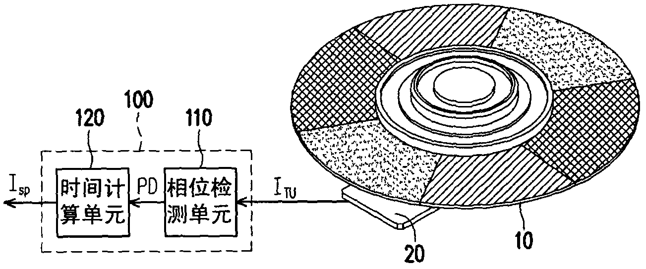
[0016] figure 1 It is a schematic diagram of a system in which a rotational speed detection device is electrically connected to a motor according to an embodiment of the present invention. Please refer to figure 1 , in this embodiment, the rotation speed detection device 100 is electrically connected to the motor 20 to receive the rotation information I output by the motor 20 TU , wherein the motor 20 is, for example, a stepping motor, and the color wheel 10 is mounted on t...


PUM


Abstract

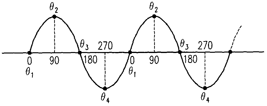
A rotation speed detecting device is provided. The rotation speed detecting device is electrically connected to a motor of a color wheel, and includes a phase detecting unit and a time calculating unit. The phase detecting unit is suitable for detecting a reference phase point of a rotation information outputted by the motor, and outputting a phase signal according to the reference phase point. The time calculating unit is electrically connected to the phase detecting unit, and calculates a speed information of the motor according to the phase signal. In this way, the rotation speed of the motor of the color wheel is correctly measured.

Description

technical field [0001] The present invention relates to a detecting device and a detecting method, and in particular to a detecting device and a detecting method for the rotating speed of a color wheel motor. Background technique [0002] The reason why a general projection device can provide a colored picture is mainly because the lighting system of the projection device can provide red, green and blue light beams in order to irradiate the light valve (light valve) in the projection device, and then make the projection device Red, green and blue images are projected sequentially on the screen. When the red, green and blue images appear in a rapid cycle in sequence, due to the persistence of vision effect of the human eye, the red, green and blue images will be mixed into a color image, which is why the projection device can provide a color image reason. [0003] Generally speaking, the lighting system allows the lighting beam to pass through a rotating color wheel, for ex...

Claims


Application Information

Patent Timeline
Patent Type & Authority Applications(China)
IPC IPC(8): G01P3/44G01P3/481
CPCG01P3/44G01P3/481
Inventor 刘瑞达
Owner CORETRONIC
Learn More