Supercharge Your Innovation With Domain-Expert AI Agents!

Drive circuit with current balance function

A technology of current balance and driving circuit, which is applied in the direction of lamp circuit layout, electric light source, lighting device, etc., and can solve problems such as difficult to provide driving current, difficult to accurately control driving current in a wide range, and large error percentage of output voltage.

Active Publication Date: 2015-03-18
LEADTREND TECH
View PDF3 Cites 0 Cited by
  • Summary
  • Abstract
  • Description
  • Claims
  • Application Information

AI Technical Summary

Problems solved by technology

[0003] However, the offset voltage (Offset Voltage) of each operational amplifier OP is not the same, so it is difficult for these current driving modules 130 to provide nearly the same driving currents Idr_1˜Idr_N to drive a plurality of diode units 190 to generate uniform output light
In addition, if the bias voltage Vb is smaller, the error percentage of the output voltage of the operational amplifier OP is larger, that is, the error percentage of the output voltage of each operational amplifier OP changes with the bias voltage Vb, so the known LED driving circuit 100 is not only It is difficult to drive multiple LED units 190 to produce uniform output light, and it is also difficult to precisely control the driving current in a wide range

Method used


Image

  • Drive circuit with current balance function
  • Drive circuit with current balance function
  • Drive circuit with current balance function

Examples


Embodiment Construction

[0042] The driving circuit with current balancing function according to the present invention will be described in detail below with reference to specific embodiments in conjunction with the accompanying drawings, but the provided embodiments are not intended to limit the scope of the present invention.

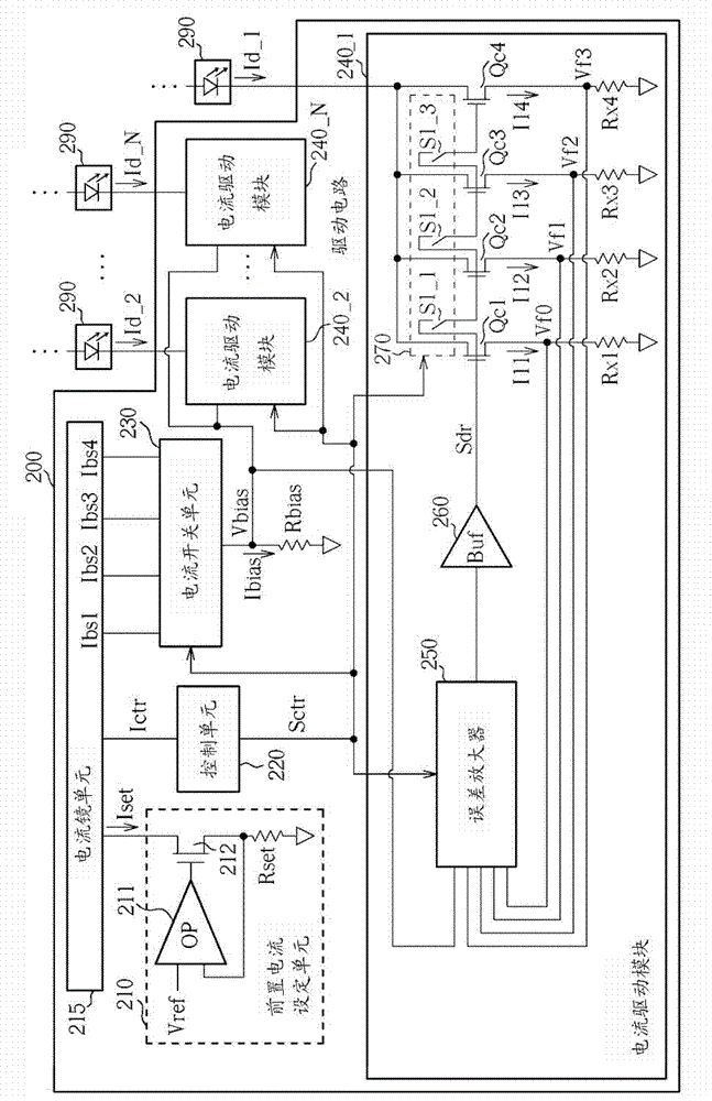
[0043] figure 2 It is a schematic diagram of the first embodiment of the drive circuit with current balance function of the present invention. In the operation of the driving circuit 200, the pre-current setting unit 210 is used to set the current through the operational amplifier 211, the transistor 212 controlled by the output voltage of the operational amplifier 211, and the current setting resistor Rset connected in series with the transistor 212 according to the reference voltage Vref. To generate the set current Iset, the current mirror unit 215 is used to output the control current Ictr and a plurality of bias voltage set currents Ibs1˜Ibs4 according to the set curren...


PUM


Abstract

The invention discloses a drive circuit with a current balance function. The circuit comprises a control unit, a bias voltage resistor, a current switch unit and a plurality of current drive modules, wherein the control unit is used for generating a control signal which comprises at least one bit according to a control current; the bias voltage resistor is used for providing a bias voltage according to a bias voltage current; the current switch unit is used for generating the bias voltage current according to the control signal and a plurality of bias voltage setting currents to maintain the bias voltage in a preset voltage range; a plurality of current drive modules are used for providing a plurality of drive currents according to the bias voltage and the control signal; and each current drive module comprises a current limit control unit, and the current limit control unit is used for controlling a corresponding drive current according to the control signal.

Description

technical field [0001] The invention relates to a driving circuit, especially a driving circuit with a current balance function. Background technique [0002] figure 1 It is a schematic diagram of a known LED driving circuit. Such as figure 1 As shown, in the operation of the LED driving circuit 100, the pre-current setting unit 110 generates the set current Ipset according to the reference voltage, the current mirror 120 outputs the bias current Ib according to the set current Ipset, and the bias resistor Rb according to The bias current Ib is used to provide a bias voltage Vb, and the plurality of current driving modules 130 provide a plurality of driving currents Idr_1˜Idr_N according to the bias voltage Vb, so as to drive the plurality of diode units 190 to emit output light with a preset brightness. The current driving module 130 utilizes the operational amplifier OP and the feedback voltage provided by the current limiting resistor Rc to perform error amplification ...

Claims


Application Information

Patent Timeline
Patent Type & Authority Patents(China)
IPC IPC(8): H05B37/02
Inventor 李敬赞林崇伟
Owner LEADTREND TECH
Features
  • R&D
  • Intellectual Property
  • Life Sciences
  • Materials
  • Tech Scout
  • Unparalleled Data Quality
  • Higher Quality Content
  • 60% Fewer Hallucinations
Learn More