
Set-top box and switching power supply circuit thereof

A switching power supply, set-top box technology, applied in the direction of electrical components, adjusting electrical variables, instruments, etc., can solve the problems of small voltage drop, small load current, high motherboard circuit voltage, etc., to achieve stable power supply voltage, reduce production costs, and high versatility Effect

Inactive Publication Date: 2012-11-28
HISENSE BROADBAND MULTIMEDIA TECH
View PDF4 Cites 14 Cited by
  • Summary
  • Abstract
  • Description
  • Claims
  • Application Information

AI Technical Summary

Problems solved by technology

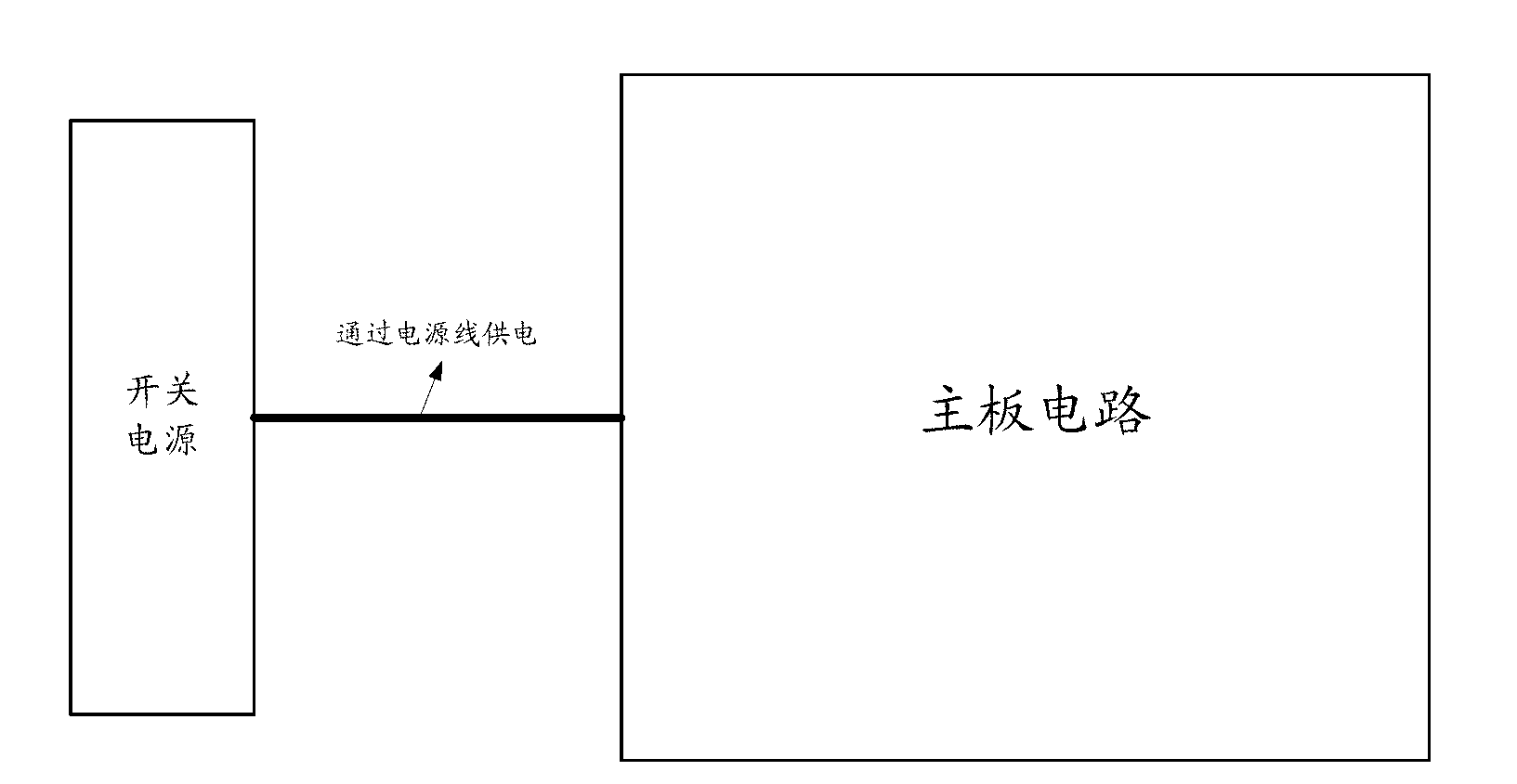
With the development of technology, on the one hand, the motherboard circuit has higher and higher requirements on the accuracy of the power supply voltage; The voltage drop generated on the power line varies greatly, which directly affects the accuracy of the supply voltage
For example, when the set-top box is in a certain working state, the load is very large, the load current is also large, and the voltage drop on the power connection line is also large, so that the voltage on the load of the main board circuit may be lower than the power supply voltage requirement. , so that some devices cannot work normally; and in another working state, the load of the set-top box is very small, the load current is also small, and the voltage drop on the power connection line is also small, which may cause the load on the motherboard circuit The voltage is too high, damage some devices
[0004] Therefore, the switching power supply adopted by the set-top box of the prior art cannot dynamically adjust the output voltage according to the load condition, and cannot guarantee the stability of the power supply voltage of the set-top box under different working conditions and different load conditions.

Method used


Image

  • Set-top box and switching power supply circuit thereof
  • Set-top box and switching power supply circuit thereof
  • Set-top box and switching power supply circuit thereof

Examples


Embodiment Construction

[0042] In order to make the object, technical solution and advantages of the present invention clearer, the present invention will be described in further detail below with reference to the accompanying drawings and preferred embodiments. However, it should be noted that many of the details listed in the specification are only for readers to have a thorough understanding of one or more aspects of the present invention, and these aspects of the present invention can be implemented even without these specific details.

[0043] As used herein, terms such as "module" and "system" are intended to include computer-related entities such as, but not limited to, hardware, firmware, a combination of hardware and software, software, or software in execution. For example, a module may be, but is not limited to being limited to being, a process running on a processor, a processor, an object, an executable, a thread of execution, a program, and / or a computer. For example, both an applicatio...


PUM


Abstract

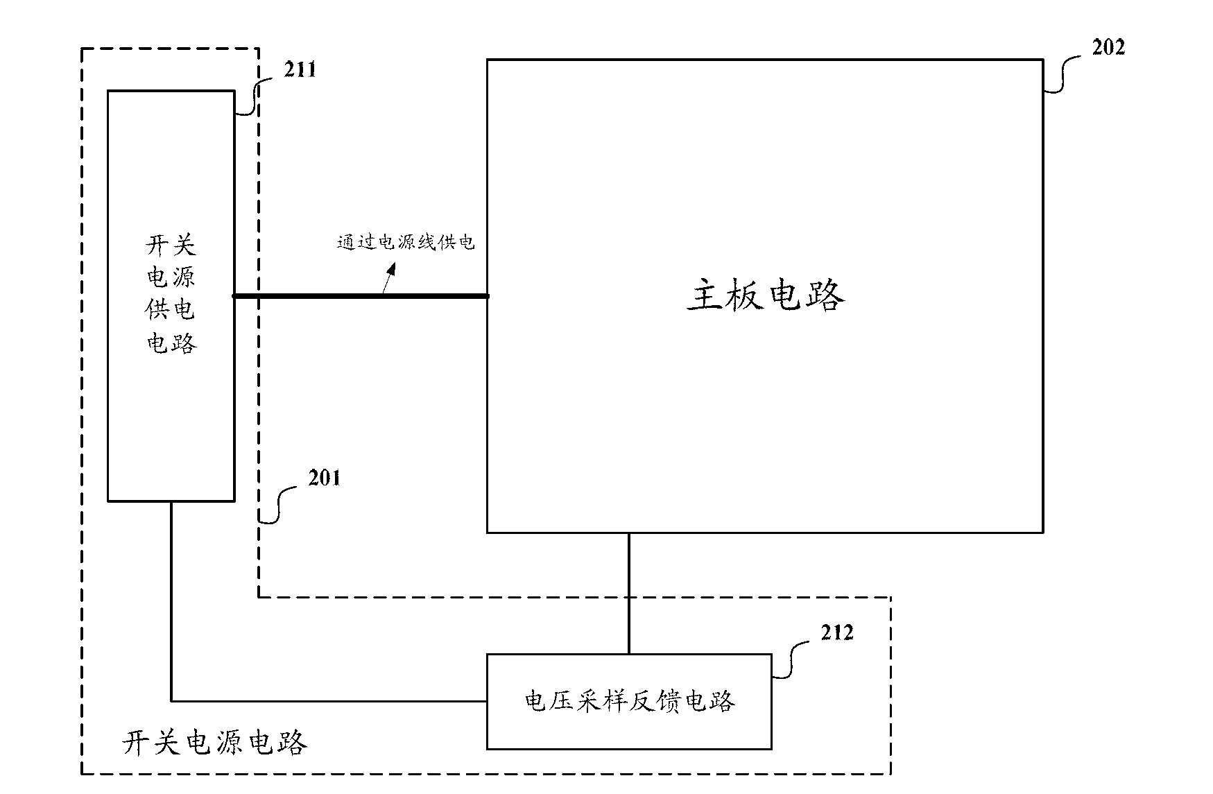
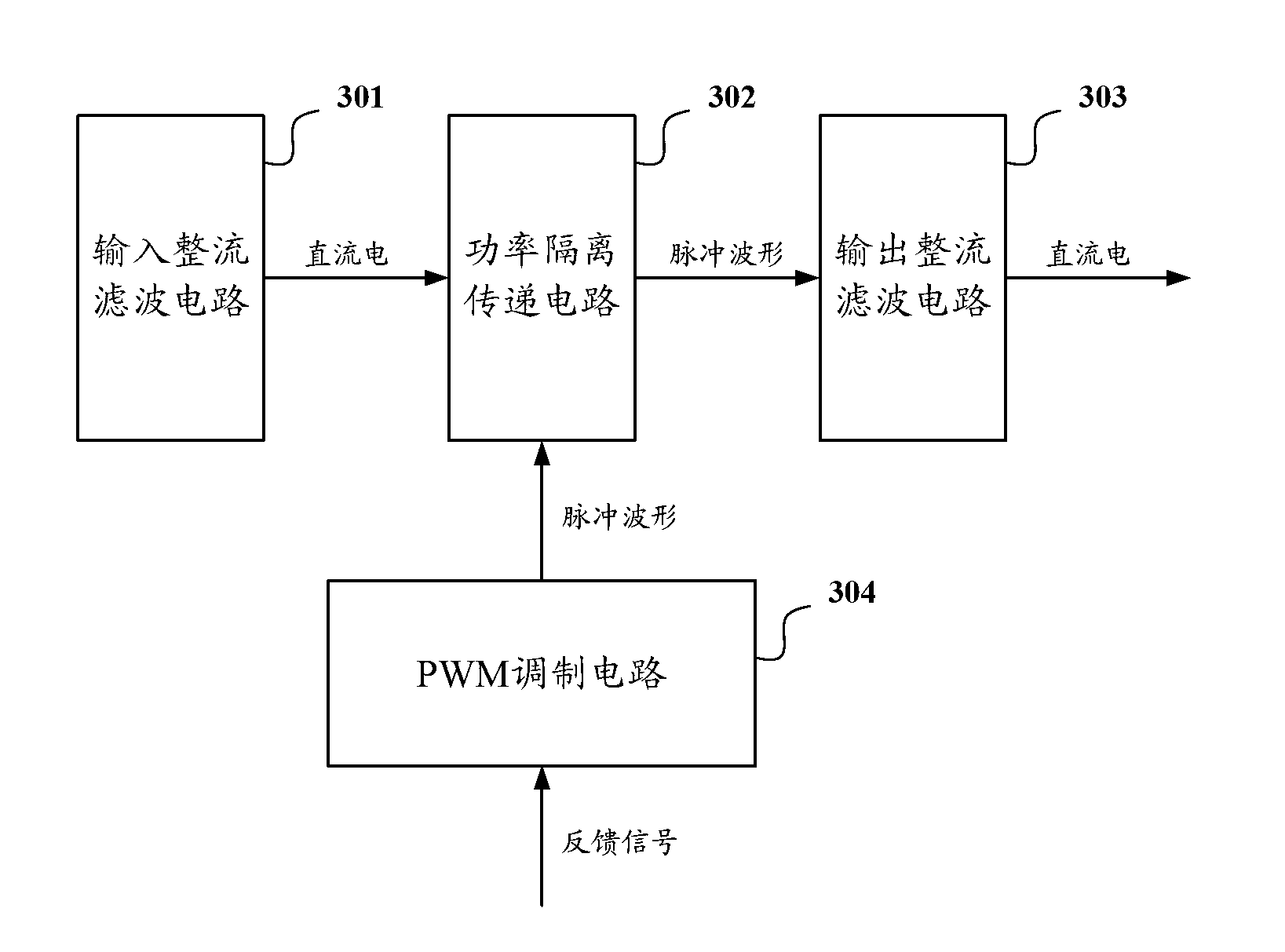
The invention discloses a set-top box and a switching power supply circuit thereof. The set top box comprises a mainboard circuit and a switching power supply circuit used for providing DC supply voltage to the mainboard circuit, wherein the switching power supply circuit comprises a voltage sampling feedback circuit used for detecting the supply voltage on the mainboard circuit and outputting a feedback signal according to the detected voltage, and a switching power supply feed circuit used for automatically regulating the DC supply voltage output to the mainboard circuit according to the received feedback signal. As the voltage sampling feedback circuit detects the supply voltage on the mainboard circuit, the feedback signal is output to the switching power supply feed circuit and the switching power supply feed circuit automatically regulates the output voltage according to the feedback signal, the stability of the supply voltage on the mainboard circuit is guaranteed.

Description

technical field [0001] The invention relates to the technology of a smart TV set-top box, in particular to a set-top box and a switching power supply circuit thereof. Background technique [0002] With the development of science and technology, digitization is getting deeper and deeper into life. At present, PCs have been intelligentized for a long time, mobile phones and tablets are also intelligentized on a large scale, and TVs are also becoming intelligent in recent years. The smart TVs currently launched have application platform advantages that traditional TVs do not have. Based on the set-top box, smart TV realizes various application services such as network search, IP TV, video on demand, digital music, network news, and network video calling. [0003] The digital set-top box with built-in power supply, its internal circuit structure is as follows figure 1 As shown, it can generally be divided into two parts: the switching power supply and the main board circuit. ...

Claims


Application Information

Patent Timeline
Patent Type & Authority Applications(China)
IPC IPC(8): H04N21/41H02M3/335
Inventor 李秀宇
Owner HISENSE BROADBAND MULTIMEDIA TECH
Learn More