
Power electronics system with first and second subsystems

A technology for power electronics and subsystems, applied in circuits, electrical components, electrical solid devices, etc., to solve problems such as inability to match, scale, and construct units

Inactive Publication Date: 2017-04-12
SEMIKRON ELECTRONICS GMBH & CO KG
View PDF6 Cites 0 Cited by
  • Summary
  • Abstract
  • Description
  • Claims
  • Application Information

AI Technical Summary

Problems solved by technology

However, this also entails the disadvantage that the system is composed of several individual components and therefore cannot be constructed as a compact unit
However, it has the disadvantage that it cannot be easily scaled due to its integration of many components and thus cannot be easily adapted to different powers

Method used


Image

  • Power electronics system with first and second subsystems
  • Power electronics system with first and second subsystems
  • Power electronics system with first and second subsystems

Examples


Embodiment Construction

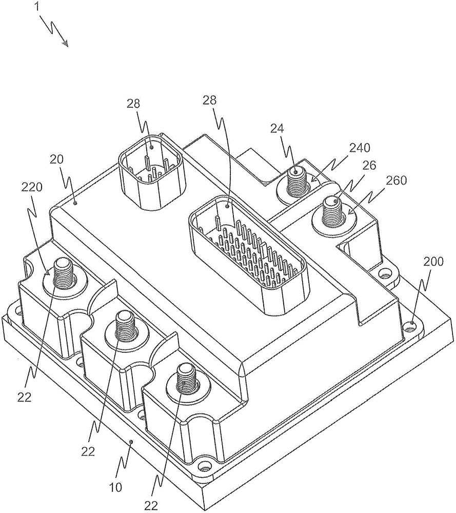
[0021] figure 1 The first power electronics system 1 according to the invention in the design of a three-phase inverter is shown in a three-dimensional illustration. A cooling device 10 , for example configured as a water cooling device, is shown schematically. The internal components of the system are covered by a housing 20 facing the cooling device 10 . The housing 10 itself is penetrated by the external coupling elements 22 , 24 , 26 at the respective recesses 220 , 240 , 260 .

[0022] Two outer DC voltage load connection elements 24 , 26 designed as screw connections are arranged on a first end side of housing 10 . On the second, opposite end side of the housing 10 , an external AC voltage load connection element 22 is shown in substantially the same technical manner.

[0023] External auxiliary coupling elements 28 are provided in two groups on the upper end side, in particular for coupling control signals and sensor signals.

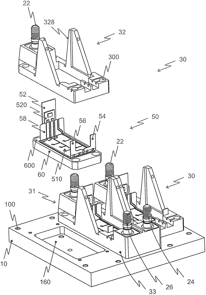
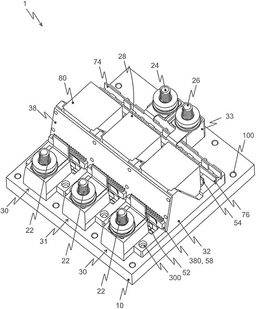
[0024] figure 2 and 3 A partially ...


PUM


Abstract

The system (1) has a subsystem comprising a switch device that is provided with a cooling component thermal conductively connected with a cooling device (10) i.e. water cooling device. Another subsystem has two external direct-current (DC) load terminal elements (24, 26) i.e. screw connections, electric-conductively connected with respective connection units such that the connection units conductively connect internal DC load terminal elements of the subsystems with the external DC load terminal elements with correct polarities. A housing (20) covers the subsystems of the cooling device. The connection units are designed as planar metallic mold-bodies.

Description

technical field [0001] The invention describes an integrated power electronics system, preferably for the construction of a circuit arrangement realized thereby in the form of a converter (for example a three-phase inverter). Such systems are preferably used in electric drives of various types of vehicles, in particular also commercial vehicles. Background technique [0002] It is basically known to construct such power electronic systems from individual power semiconductor modules, for example according to DE 10 2009 037 257 A1, by means of external wiring, ie by connecting external connecting elements of the power semiconductor modules to one another. Such a system has the advantage that it can be adjusted to the required power arbitrarily by scaling. However, this also entails the disadvantage that the system is composed of a plurality of individual components and therefore cannot be constructed as a compact unit. [0003] It is also known to design such power electroni...

Claims


Application Information

Patent Timeline
Patent Type & Authority Patents(China)
IPC IPC(8): H01L23/48H01L25/07H01L23/34
CPCH01L25/072H01L23/4006H01L23/473H01L25/162H01L2924/0002H01L2924/00
Inventor 托马斯·弗兰克赖纳·波普斯特凡·魏斯
Owner SEMIKRON ELECTRONICS GMBH & CO KG
Learn More