heating cooker
A cooking device and heating chamber technology, applied in electric heating fuel, lighting and heating equipment, household heating, etc., to achieve the effect of good convenience
- Summary
- Abstract
- Description
- Claims
- Application Information
AI Technical Summary
Problems solved by technology
Method used
Image

Examples
Embodiment approach 1
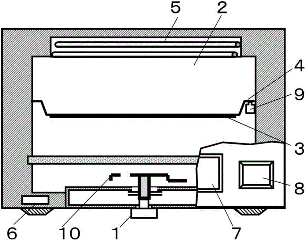
[0031] figure 1 A cross-sectional view of the heating cooker according to Embodiment 1 of the present invention is shown. The heating cooker of this embodiment includes: a microwave generating unit 1; a heating chamber 2 that accommodates a load to be heated; and a heating plate 4 that has a heating element 3 that absorbs microwaves and generates heat, and is arranged so as to divide the heating chamber 2 up and down. The upper surface heating unit 5 heats the upper surface side of the heating plate 4 ; and the control unit 6 controls the input power of the microwave generating unit 1 and the upper surface heating unit 5 .
[0032] Usually, a magnetron is often used for the microwave generating unit 1 , but a semiconductor type or the like may be used. According to an instruction from the control unit 6 , power is supplied to the microwave generating unit 1 from an inverter circuit not shown in the figure, thereby causing the microwave generating unit 1 to generate microwaves...
Embodiment approach 2
[0065] Next, Embodiment 2 of the present invention will be described. The description of the same parts as those in Embodiment 1 will be omitted, and only the different points will be described.
[0066] The display unit 7 displays a heating method and the like. Most of such heating cookers have a variety of heating methods such as heating based on microwaves, heating based on steam, heating based on heaters, and heating based on ovens. Usually, the user selects the heating method and determines the heating time for heating. Or, it also has the following functions: select the automatic cooking mode stored in the heating cooker, adjust the heating method and time corresponding to the menu that the user wants to make by sensors, etc. to automatically heat, and when the heating is finished, it will automatically stop. Heat and inform user. In order to select these functions, information for selecting a heating method, heating time, automatic menu, etc. is displayed on the displ...
Embodiment approach 3
[0073] Next, Embodiment 3 of the present invention will be described. The description of the same parts as those in Embodiment 1 will be omitted, and only the different points will be described.
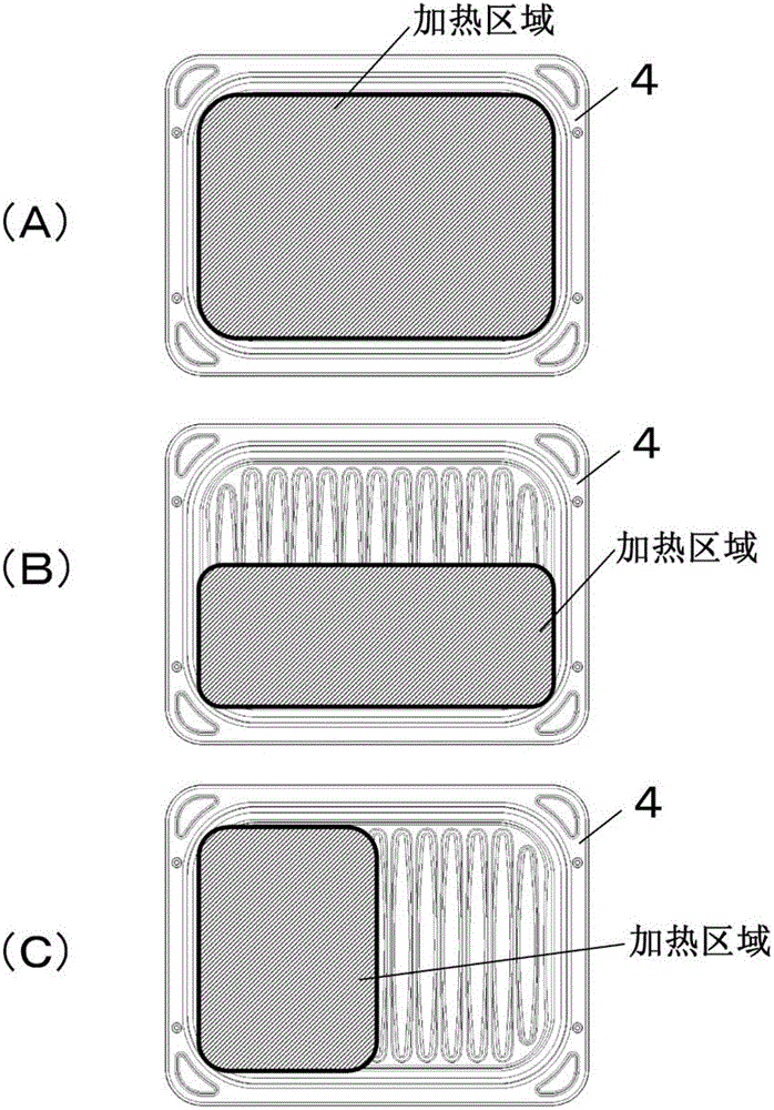
[0074] In this embodiment, there is provided a heating cooker configured to limit the direction in which the heat generating disk is inserted to one direction when the heat generating disk is inserted into the heating chamber.
[0075] In the case where the insertion direction of the heating plate 4 is not specified, such as Figure 4 As shown, it is necessary to display in various directions in order to indicate where the heating area is when concentrated heating is performed. At this time, many characters and the like are displayed on the heating plate 4, and as a result, there is a possibility that the display becomes difficult to understand.
[0076] Therefore, the heating disk 4 and the heating chamber 2 are configured in such a way that the direction in which the heating disk...
PUM
 Abstract
Description
Claims
Application Information
 - R&D
- Intellectual Property
- Life Sciences
- Materials
- Tech Scout
- Unparalleled Data Quality
- Higher Quality Content
- 60% Fewer Hallucinations
Browse by: Latest US Patents, China's latest patents, Technical Efficacy Thesaurus, Application Domain, Technology Topic, Popular Technical Reports.
© 2025 PatSnap. All rights reserved.Legal|Privacy policy|Modern Slavery Act Transparency Statement|Sitemap|About US| Contact US: help@patsnap.com