
Disc-type permanent magnet motor with sealed cooling structure

A permanent magnet motor and cooling structure technology, applied in electric components, cooling/ventilation devices, electromechanical devices, etc., can solve the problems of winding temperature rise, motor burning, permanent magnet corrosion, etc., to increase the heat dissipation area and ensure cooling effect, the effect of prolonging the service life

Inactive Publication Date: 2012-11-21
BOHAI UNIV
View PDF7 Cites 12 Cited by
  • Summary
  • Abstract
  • Description
  • Claims
  • Application Information

AI Technical Summary

Problems solved by technology

Compared with the motor with radial structure, this heat dissipation method has the following defects: 1. The open structure is easy to corrode the permanent magnet and shorten the service life of the disc permanent magnet motor
2. The heat dissipation method of natural air cooling requires a ventilated, cool and dry environment, and the layout of the disc permanent magnet motor is difficult to meet the above environmental requirements
3. The heat dissipation area of ​​the disc permanent magnet motor is much smaller than that of the radial structure motor, the heat dissipation speed is slow, and the winding temperature rises, which limits the improvement of the power density of the disc permanent magnet motor
The disadvantages of this cooling method are: 1. The fluid cooling area is small and can only cool the windings. The temperature of each part of the disc permanent magnet motor is uneven, which can easily lead to local overheating and burn the motor.
2. The cavity of the coolant flow chamber has a large capacity, and the newly injected coolant is mixed in the coolant flow chamber, and the temperature rises, resulting in a small temperature difference between the coolant and the winding, and poor cooling effect

Method used


Image

  • Disc-type permanent magnet motor with sealed cooling structure
  • Disc-type permanent magnet motor with sealed cooling structure
  • Disc-type permanent magnet motor with sealed cooling structure

Examples


Embodiment Construction

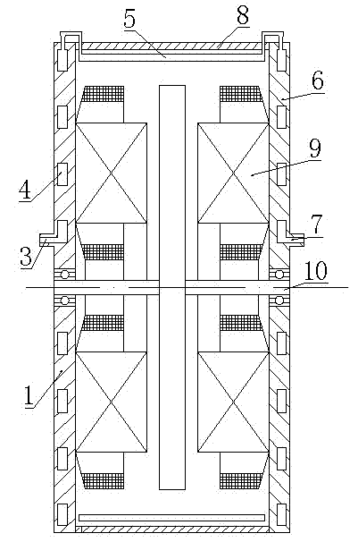
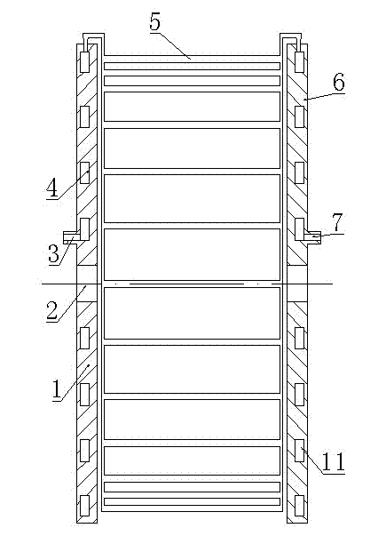
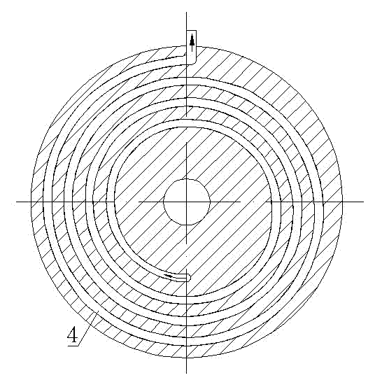
[0024] As shown in the figure, the disc permanent magnet motor with a closed cooling structure includes a casing 8, a driving side end cover 1 and a non-driving side end cover 6 arranged on both sides of the casing 8, and the driving side end cover 1 and the non-driving side The center of the end cover 6 is respectively provided with a shaft hole 2, and windings 9 are respectively installed on the driving side end cover 1 and the non-driving side end cover 6, and the two windings 9 are respectively the driving side winding and the non-driving side winding. A rotating shaft 10 is arranged between the holes 2 . In the end cover 1 on the driving side and the end cover 6 on the non-driving side, a spiral end cover water channel I4 and an end cover water channel II11 are respectively provided, and the rotation directions of the end cover water channel I4 and the end cover water channel II11 are opposite. In this embodiment , the rotation direction of the end cap water channel I4 is...


PUM


Abstract

The invention discloses a disc-type permanent magnet motor with a sealed cooling structure. The disc-type permanent magnet motor comprises a casing, and a drive side end cover and a non-drive side end cover which are arranged at the two sides of the casing, shaft holes are arranged at the centers of the drive side end cover and the non-drive side end cover; windings are respectively arranged on the drive side end cover and the non-drive side end cover; and a rotating shaft is arranged between the two shaft holes. The disc-type permanent magnet motor is characterized in that a spiral end cover water channel I and an end cover water channel II are respectively arranged inside the drive side end cover and the non-drive side end cover, and the outlet of the end cover water channel I and the inlet of the end cover water channel II are respectively arranged on the outer brims of the drive side end cover and the non-drive side end cover; a water inlet communicated with the inlet of the end cover water channel I is arranged on the drive side end cover; a water outlet communicated with the outlet of the cover water channel II is arranged on the non-drive side end cover; and the outlet of the end cover water channel I and the inlet of the end cover water channel II are communicated with a plurality of built-in direct water channels distributed along the circumference. The disc-type permanent magnet motor has the advantages that the radiating speed is fast; the cooling effect is good; the power density is high; the service life is long; the temperature of the components is balanced; and the disc-type permanent magnet motor is not burnt up due to local overheat.

Description

technical field [0001] The invention relates to a disc type permanent magnet motor with a closed cooling structure. Background technique [0002] The disc permanent magnet motor has the characteristics of simple structure, small size, light weight and high efficiency. Rotor with permanent magnets. Most of the existing disc permanent magnet motors are open structures, which are cooled by natural air cooling, and the heat generated by the windings and the stator core is dissipated through the stator core and the end cover. Compared with the radial structure motor, this heat dissipation method has the following defects: 1. The open structure easily causes the permanent magnet to be corroded, shortening the service life of the disc permanent magnet motor. 2. The heat dissipation method of natural air cooling requires a ventilated, cool and dry environment, and the layout of the disc permanent magnet motor is difficult to meet the above environmental requirements. 3. The heat ...

Claims


Application Information

Patent Timeline
Patent Type & Authority Applications(China)
IPC IPC(8): H02K9/19H02K5/20
Inventor 王巍伦淑娴郭艳东杨菲韩志艳周建壮苏宪利
Owner BOHAI UNIV
Learn More