
Lens drive device

A technology of lens driving device and lens sheet, which is applied in the direction of electromechanical devices, projection devices, printing devices, etc., can solve the problems such as the reduction of thrust linearity of lens holding parts and the inability of the magnetic field to act uniformly, and achieve the effect of maintaining linearity

Active Publication Date: 2015-02-25
ALPS ALPINE CO LTD
View PDF6 Cites 0 Cited by
  • Summary
  • Abstract
  • Description
  • Claims
  • Application Information

AI Technical Summary

Problems solved by technology

However, in the above-mentioned lens driving device, considering the interference between the inner wall portion of the yoke and the flange portion of the lens holding member, it is not possible to secure a sufficient length for the inner wall portion to match the winding width of the coil.
Therefore, the magnetic field cannot be uniformly applied to the coil through the inner wall portion and the magnet, and the thrust and linearity of the lens holding member are reduced.

Method used


Image

  • Lens drive device
  • Lens drive device
  • Lens drive device

Examples


Embodiment Construction

[0025] Specific embodiments of the present invention will be described in detail below with reference to the accompanying drawings. In addition, the following lens drive device is only an example, and this invention is not limited to this embodiment.

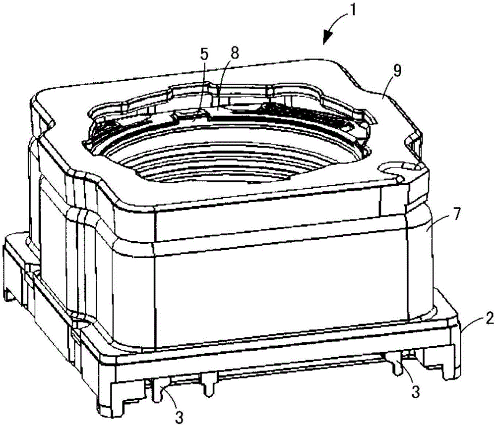
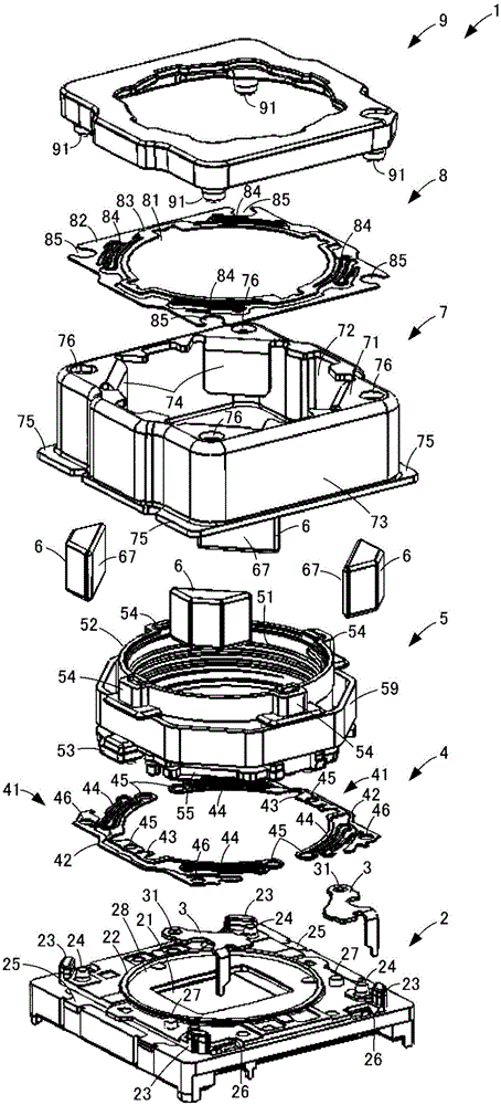
[0026] figure 1 This is an overall perspective view of the lens driving device according to the present embodiment. figure 2 This is an exploded perspective view of the lens driving device according to the present embodiment.

[0027] like figure 1 as well as figure 2 As shown, the lens driving device 1 is mounted on a substrate on which an image sensor (not shown in the figure) is attached as an imaging element, and drives a lens body (not shown in the figure) in the optical axis direction with respect to the image sensor. to adjust the focus distance. In the lens driving device 1 , on the chassis 2 on which the external terminals 3 are mounted, the lens holding member 5 is mounted via the lower leaf spring 4 . A coil 5...


PUM


Abstract

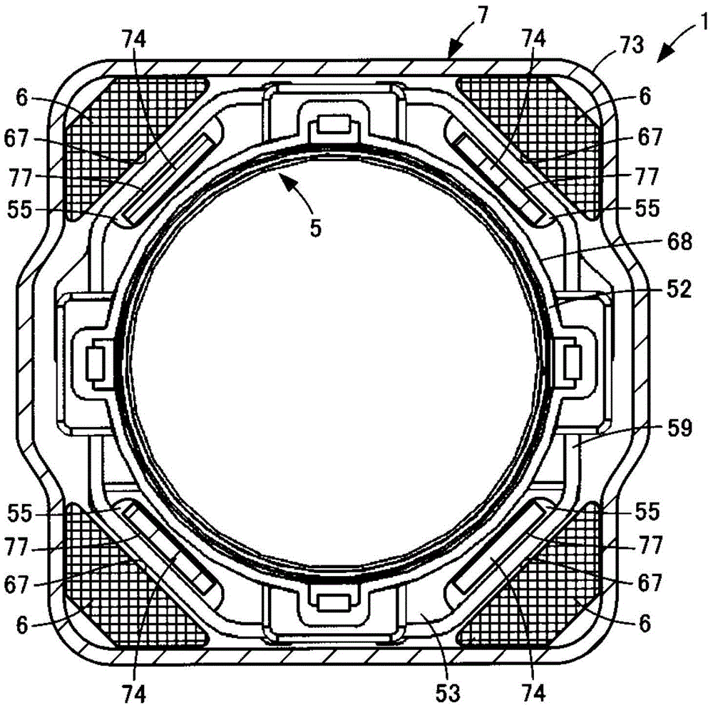
The invention provides a lens drive device which can maintain the push force and linearity of a lens retaining component even if the width of a coil is reduced. The lens drive device comprises a lens retaining component (5) for retaining a lens body, a coil (59) which is disposed on the lens retaining component (5) and forms a gap with the outer circumferential face (68) of an optical axis of the lens retaining component (5), a yoke part (7) which includes an outer wall part (73) encircling the outer side of the coil (59) and an inner wall part (74), where the gap of the inner side of the coil (59) is disposed opposite to the outer wall part (73), and a magnet (6) which forms a magnetic circuit acting on the coil (59) with the yoke part (7). The outer circumferential face (68) of the lens retaining component (5) is provided with a flange part (53) which is opposite to the end part of the inner wall part (74) in the direction of the optical axis. The flange part (53) is provided with an avoiding part (55) where an end part of the inner wall part (74) can enter.

Description

technical field [0001] The present invention relates to a small lens driving device mounted on a mobile phone with a camera or the like. Background technique [0002] Conventionally, as a small lens driving device, there is known a device that magnetically drives a lens holding member holding a lens in the optical axis direction (for example, refer to Patent Document 1). The lens driving device described in Patent Document 1 has a structure in which a lens holding member with a coil mounted thereon is placed on a base member, and the yoke portion is covered from the upper side. The lens holding member has a cylindrical portion for fixing the lens unit inside, and a flange portion protruding outward from a lower portion of the cylindrical portion. On the flange portion of the lens holding member, a coil is attached with a gap from the outer peripheral surface of the cylindrical portion. [0003] The yoke has an outer peripheral wall portion surrounding the coil radially out...

Claims


Application Information

Patent Timeline
Patent Type & Authority Patents(China)
IPC IPC(8): G02B7/04G03B13/34H02K33/18
Inventor 中岛尚伊藤清行石黑克之大友胜彦
Owner ALPS ALPINE CO LTD
Learn More