
Power factor correction device

A power factor correction, DC output technology, applied in output power conversion devices, high-efficiency power electronic conversion, electrical components, etc., can solve problems such as reduced power efficiency, AC current distortion, and damage to substation equipment to improve utilization. Effect

Inactive Publication Date: 2012-11-14
中山市爱的圣科技有限公司
View PDF6 Cites 0 Cited by
  • Summary
  • Abstract
  • Description
  • Claims
  • Application Information

AI Technical Summary

Problems solved by technology

When the AC power is converted into DC, since the power rectifier is a nonlinear component, the input AC current will be distorted and pulse-like. The serious consequences will be the harmful effect of harmonics on the power grid, damage to the substation equipment, and reduced power efficiency. cause waste of energy
However, the existing active non-full-following power factor correction circuit can improve the stable value to a certain extent, but the cost is high and the efficiency is low.

Method used


Image

  • Power factor correction device
  • Power factor correction device
  • Power factor correction device

Examples


Embodiment Construction

[0016] The present invention will be described in detail below in conjunction with the accompanying drawings and specific embodiments, but it is not intended to limit the present invention.

[0017] from figure 1 It can be seen from the figure that the embodiment of the present invention uses CCN to realize the active full-following power factor correction, which is powered by the AC power supply 1 to the EMC circuit 2, and the EMC circuit 2 is then passed through the AC / DC rectifier bridge 3 and the PFC circuit 4. Realize high-efficiency conversion of AC current into DC current to supply power to DC load 5 .

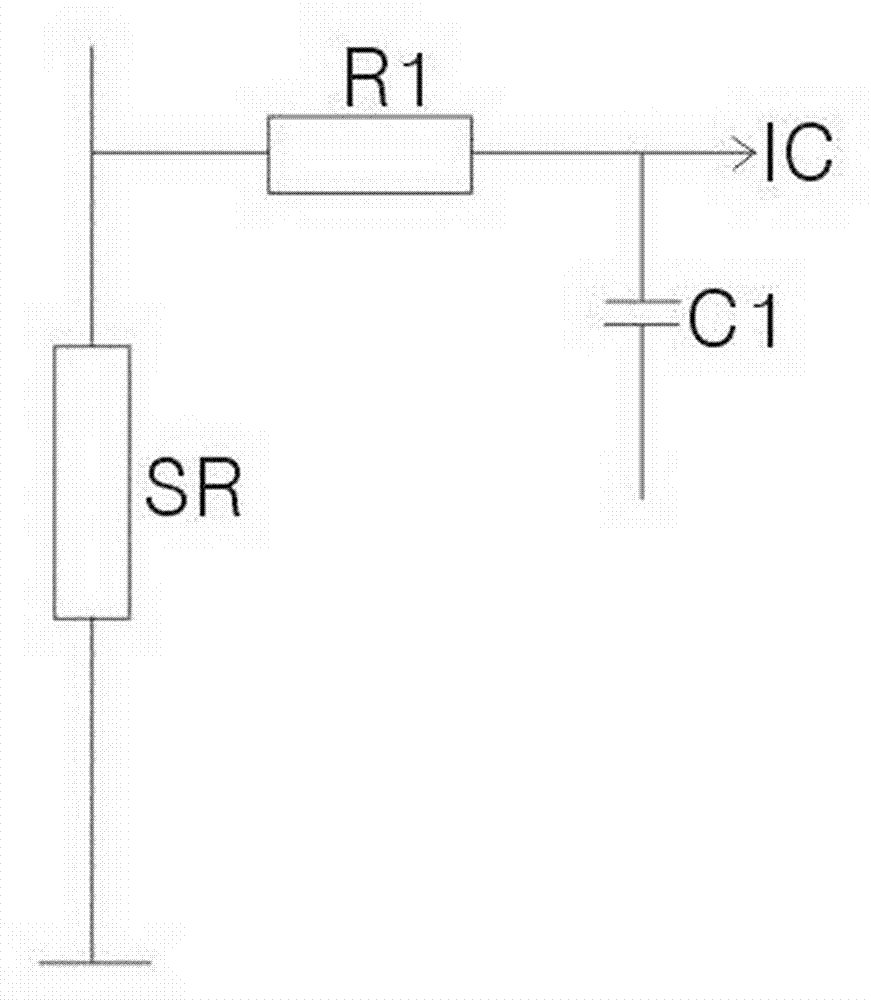
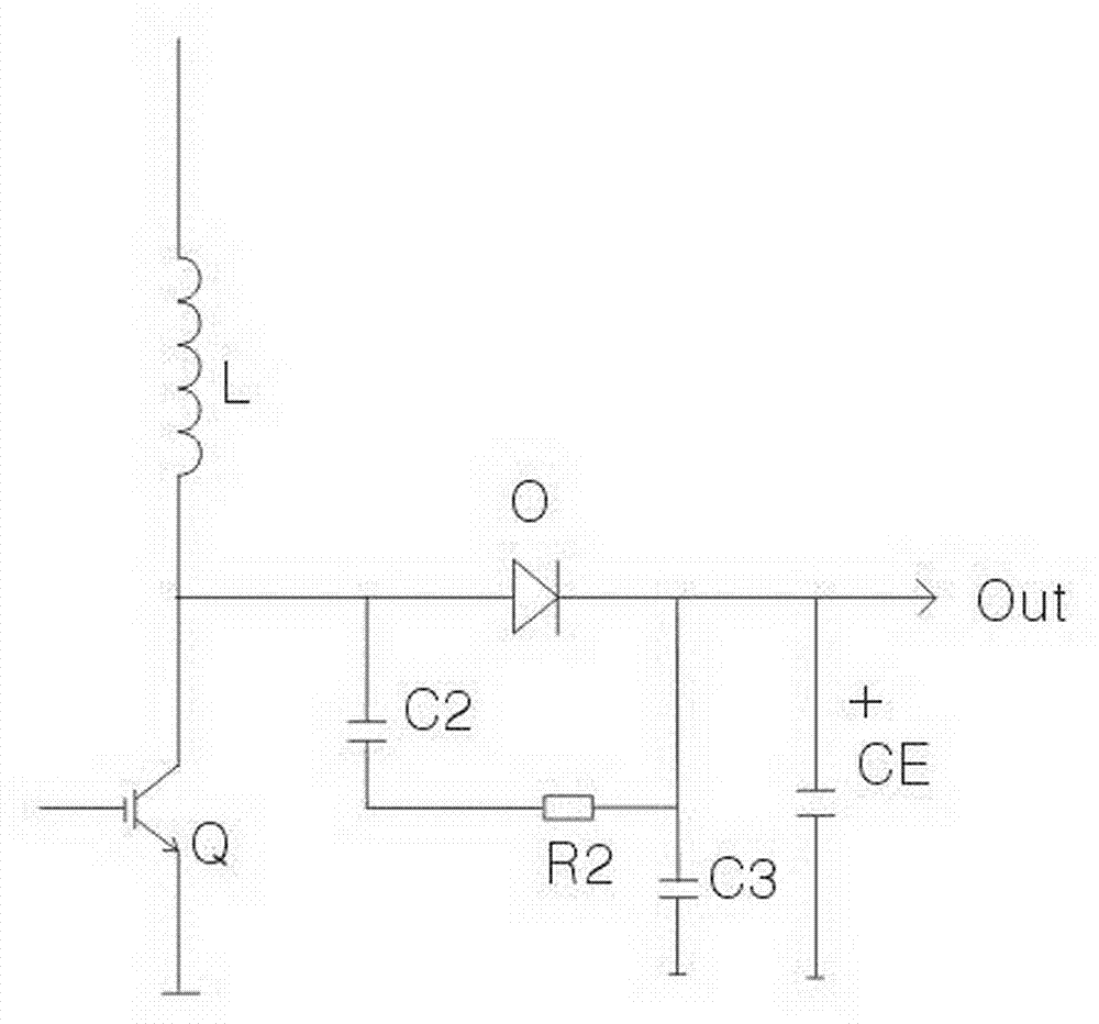
[0018] refer to figure 2 and image 3 , the PFC circuit in this power factor correction device includes an IC chip, a current detection resistor, a switch tube Q, an inductor L and a DC output terminal; wherein the current detection resistor is a non-inductive resistor SR with high power and small impedance to improve the power bearing capacity of the cir...


PUM


Abstract

The invention relates to the field of power factor control, particularly to a power factor correction device, which is mainly used for active fully-following type power factor correction of a single PFC (power factor correction) control IC (integrated circuit). The power factor correction device comprises an IC chip, a current detection resistor, a switch tube, an inductor and a direct-current output end. The power factor correction device is characterized in that the current detection resistor is a non-inductive resistor, the switch tube is an IGBT (insulated gate bipolar translator) switch tube, the inductor is a high-frequency magnetic ring inductor with a plurality of enamelled wires, and a resistance capacitor and a high-frequency removal capacitor are arranged at the direct-current output end. The stable, efficient and compact effects of a high-power active fully-following type power factor correction circuit are realized by partially changing the current detection resistor, the switch tube, the inductor and the direct-current output end, thus increasing the utilization rate of electric energy.

Description

technical field [0001] The invention relates to the field of power factor control, in particular to a power factor correction device, which is mainly used for active full-following power factor correction of a single-chip PFC control IC. Background technique [0002] The current mains is a standard sine wave, and the current flowing through the resistive load is also a sine wave with the same phase. When the AC power is converted into DC, since the power rectifier is a nonlinear component, the input AC current will be distorted and pulse-like. The serious consequences will be the harmful effect of harmonics on the power grid, damage to the substation equipment, and reduced power efficiency. cause energy waste. However, the existing active non-full-following power factor correction circuit can improve the stable value to a certain extent, but the cost is high and the efficiency is low. Contents of the invention [0003] The invention aims at the deficiencies o...

Claims


Application Information

Patent Timeline
Patent Type & Authority Applications(China)
IPC IPC(8): H02M1/42
CPCY02B70/126Y02B70/10
Inventor 陈旭亮
Owner 中山市爱的圣科技有限公司
Learn More