Backlight module

A backlight module and backplane technology, applied in the direction of optics, electric light source, light source fixation, etc., can solve the problems of backlight module temperature rise, warpage, affecting light guide function, etc., to avoid taste and brightness, reduce warpage probability, and the effect of improving light extraction efficiency

Inactive Publication Date: 2012-11-14
LEXTAR ELECTRONICS CORP
View PDF2 Cites 13 Cited by
  • Summary
  • Abstract
  • Description
  • Claims
  • Application Information

AI Technical Summary

Problems solved by technology

The heat generated by the light-emitting diodes is likely to cause the temperature of the backlight module to rise. Due to the effect of thermal expansion and contraction, the light guide plate is easily deformed and warped
Especially when the light guide plate has no space for deformation, the problem of its thermal deformation affecting the light guide function is more serious

Method used


Image

  • Backlight module
  • Backlight module
  • Backlight module

Examples


no. 1 example

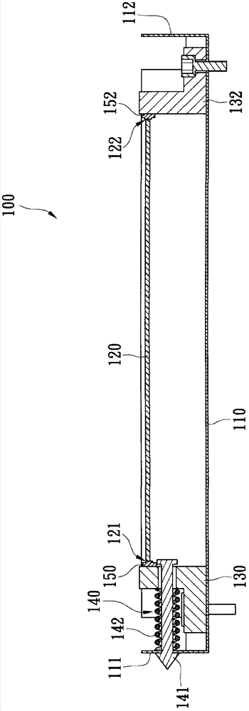
[0030] figure 1 A schematic cross-sectional structure diagram of the backlight module according to the first embodiment of the present invention is shown. The backlight module 100 includes a backplane 110 , a light guide plate 120 , cooling elements 130 , 132 , elastic elements 140 and light bars 150 , 152 . The backboard 110 has two parallel sidewalls 111 , 112 , which are formed by two mutually parallel edges of the backboard 110 protruding upward in a direction perpendicular to the surface of the backboard 110 . The accommodating space formed by the back plate 110 is suitable for assembling components such as the light guide plate 120 , the heat dissipation elements 130 , 132 , the elastic element 140 , and the light bars 150 , 152 .

[0031] The light guide plate 120 is disposed on the back plate 110 and has two light incident sides 121 , 122 parallel to each other. According to its position, the two light incident sides 121 , 122 correspond to the side walls 111 , 112 re...

no. 2 example

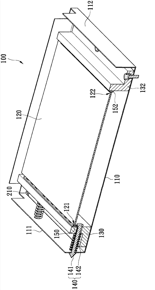
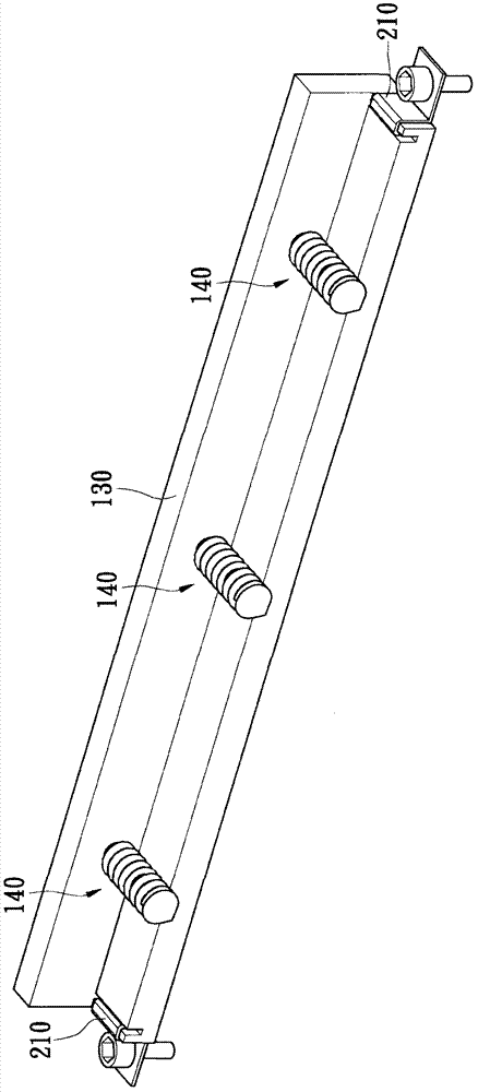
[0040] The light source structures on both sides of the light guide plate 120 can be movable structures, such as Figure 5 and Image 6 as shown, Figure 5 A schematic cross-sectional structure diagram showing the backlight module of the second embodiment of the present invention, Image 6 A schematic diagram showing the three-dimensional structure of the backlight module according to the second embodiment of the present invention. The heat dissipation elements 130, 133 located on both sides of the light guide plate 120 are movably arranged on the back plate 110, and are respectively provided with at least one elastic element 140 and 145, so that the light strips 150, 152 on the heat dissipation elements 130, 133 can be closely abutted against On the two light incident sides 121 , 122 of the light guide plate 120 . Both sides of the cooling element 133 are provided with limiting elements 212 similar in structure to the limiting element 210 , which can be used to limit the s...


PUM


Abstract

The invention provides a backlight module, comprising a backplane, a light guide plate, a chatoyancy and a heat dissipation element. The heat dissipation element is arranged on the backplane movably, and the chatoyancy is abutted against the light guide plate tightly via an elastic element abutted between the side wall of the backplane and the heat dissipation element to form a gapless light source structure, thereby improving the outgoing light efficiency. The chatoyancy abutted against the light guide plate can move along with the heat dissipation element, so that the space needed by the light guide plate heated deformation can be supplied to reduce the deformation probability of the light guide plate.

Description

technical field [0001] The invention relates to a backlight module, and in particular to a backlight module with no gap between a light strip and a light guide plate. Background technique [0002] The backlight module of the LCD TV is used to provide a uniform surface light source to the LCD panel, and it usually consists of a back bezel, a light guide plate and a light source. The light from the light source can enter the light guide plate from the side of the light guide plate, and then form a surface light source through refraction and reflection for the LCD TV. [0003] Generally speaking, the components of the backlight module are locked together by structures or screws, and the positions of the light guide plate and the light source are fixed and cannot be adjusted automatically. For the convenience of assembly, there will be a gap between the light guide plate and the light source. However, if the gap between the light guide plate and the light source is too large, ...

Claims


Application Information

Patent Timeline
Patent Type & Authority Applications(China)
IPC IPC(8): F21S8/00F21V15/00F21V17/00F21V19/00G02F1/13357
Inventor 李炽昌吴有章
Owner LEXTAR ELECTRONICS CORP
Why Eureka
Try Eureka