
Spinning device for air exhaust type rotor spinning machine

A technology of rotor spinning machine and spinning machine, which is applied in spinning machine, open-end spinning machine, continuous winding spinning machine, etc. Quality reduction and other problems, to achieve the effect of stable positioning, convenient installation and replacement

Active Publication Date: 2012-11-14
WENLING RISHENG MACHINERY
View PDF9 Cites 6 Cited by
  • Summary
  • Abstract
  • Description
  • Claims
  • Application Information

AI Technical Summary

Problems solved by technology

However, the fixing method between the rotor base and the spinner housing of the spinner of the existing air-pumping spinning machine adopts the mode of pressing against the lower surface of the rotor base so that the gap between the rotor base and the spinner housing is fixed. In the actual work process, due to the vibration of the spinning machine and the long-term use of the spinning machine, etc., it will cause looseness between the spinner shell and the rotor seat, which will affect the negative pressure. The tightness of the cavity, but also the wear of the machine, the increase of noise and the reduction of yarn quality

Method used


Image

  • Spinning device for air exhaust type rotor spinning machine
  • Spinning device for air exhaust type rotor spinning machine
  • Spinning device for air exhaust type rotor spinning machine

Examples


Embodiment Construction

[0041] The following are specific embodiments of the present invention and in conjunction with the accompanying drawings, the technical solutions of the present invention are further described, but the present invention is not limited to these embodiments.

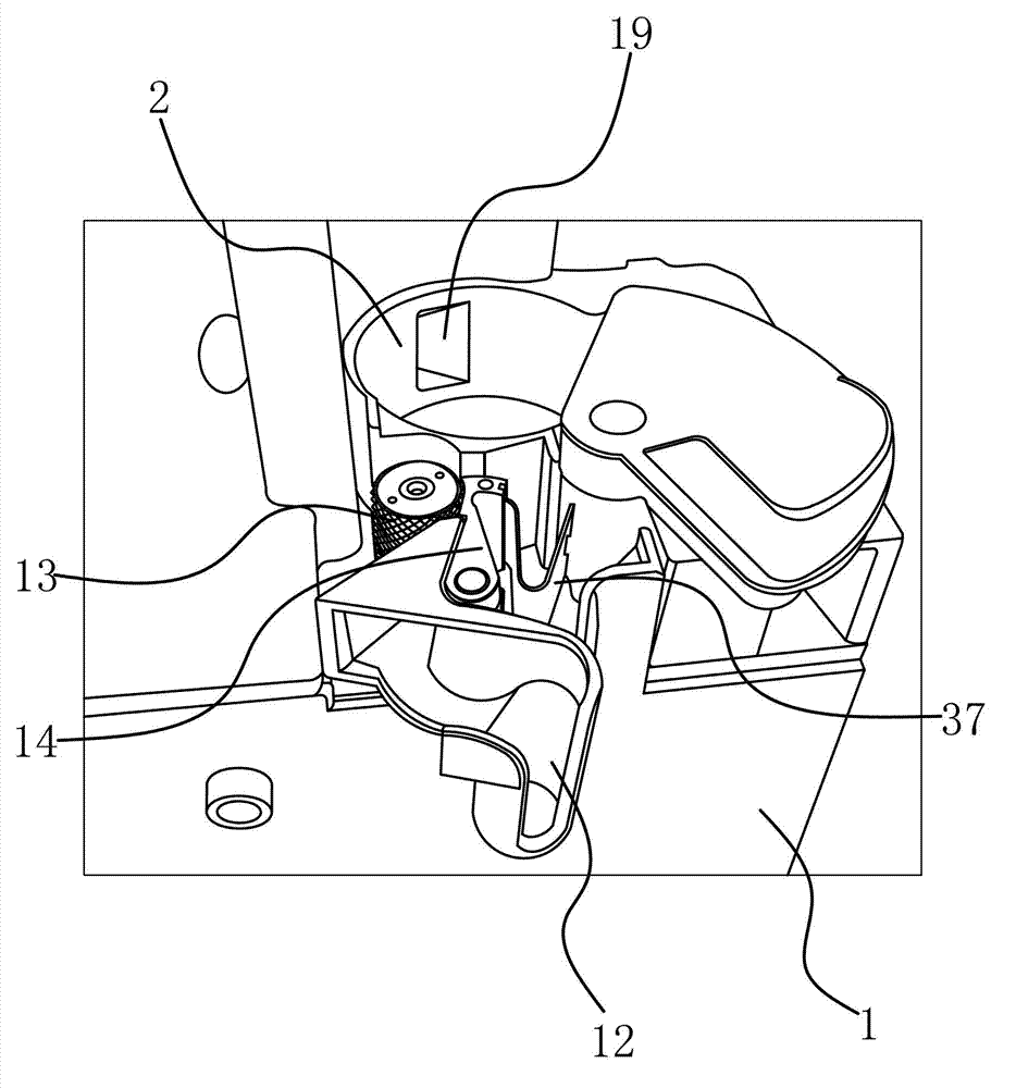
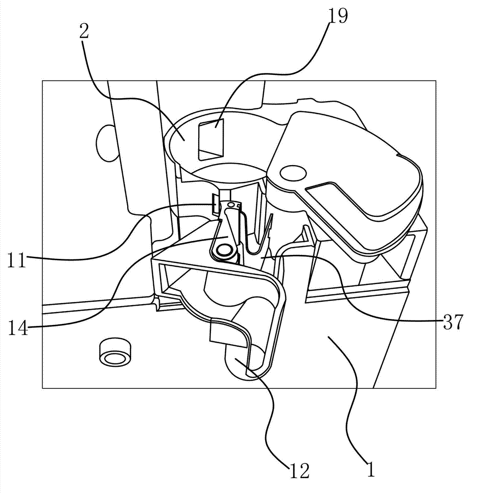
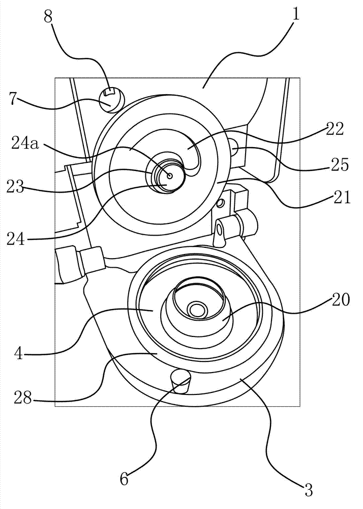
[0042] The spinning device of the air suction rotor spinning machine includes a housing 1, on which a cotton feeding device, a miscellaneous removal device, a rotor device, a rotor seat 3 and a yarn guide tube 5 are arranged. The cotton feeding device feeds the cotton sliver into the carding device, and the carding device combs the cotton sliver into single fibers. During the carding process, the impurities on the cotton sliver are discharged from the waste removal device, and the single fiber enters under the action of negative pressure. The rotor device forms a sliver in the rotor device and leads from the yarn guide tube 5 .

[0043] Specifically, such as figure 1 , figure 2 , image 3 with Figure 4 As shown, the ...


PUM


Abstract

The invention provides a spinning device for an air exhaust type rotor spinning machine, and belongs to the technical field of spinning machines, solving the technical problems of current spinning device for the air exhaust type rotor spinning machine that a spinning rotor holder cannot be firmly positioned, and the spinning device is inconvenient to use, etc. The spinning device for the air exhaust type rotor spinning machine comprises a housing body with a carding chamber, wherein a cotton feeding device, a cotton device and an inclusions removing device are arranged on the housing body; the spinning rotor holder is hinged on the housing body, and provided with a negative pressure chamber on the spinning rotor holder; the negative pressure chamber is communicated with the carding chamber; a rotor device for integrally twisting a plurality of single fibers is also arranged in the negative pressure chamber; and a yarn guiding pipe is arranged on the housing body; when the spinning rotor holder is clung to the housing body, the negative pressure chamber is communicated with the outside through the yarn guiding pipe, thus the fiber in the negative pressure chamber can be guided out of the housing body through the yarn guiding pipe; and a fixing device for adhering and fixing the spinning rotor holder to the housing body is arranged between the spinning rotor holder and the housing body. The spinning device for the air exhaust type rotor spinning machine has the advantages that the housing body is firmly fixed to the spinning cup holder, and the spinning device is stable in running, etc.

Description

technical field [0001] The invention belongs to the technical field of spinning machines, and relates to a spinning device of an air suction rotor spinning machine. Background technique [0002] With the improvement of people's living standards and the rapid development of the textile industry, various spinning methods have emerged. Among various new spinning methods and technologies, the rotor spinning machine is It has the advantages of large capacity, good spinnability of low-grade cotton and waste noil, etc. It has replaced the traditional ring spinning machine and has become the main force in the machine spinning technology, and has become the most mature technology in the new spinning. The spinning form with the widest application and great economic and social effects. Since the first KS-200 rotor spinning prototype machine was successfully developed in the Czech Republic in 1965, it has a history of more than 40 years. The rotor spinning products have developed from ...

Claims


Application Information

Patent Timeline
IPC IPC(8): D01H4/30D01H4/10
Inventor 朱琴华
Owner WENLING RISHENG MACHINERY
Learn More