
Device comprising a ring cylinder and a ring piston

A ring-shaped piston and ring-shaped cylinder technology, applied in the direction of non-mechanical drive clutches, fluid drive clutches, clutches, etc., can solve the problems of complex manufacturing process, easy scratches, and easy damage to the paint layer, and achieve low-cost manufacturing and assembly. Effect of weight, simplified assembly

Inactive Publication Date: 2012-11-07
WABCO GMBH
View PDF13 Cites 4 Cited by
  • Summary
  • Abstract
  • Description
  • Claims
  • Application Information

AI Technical Summary

Problems solved by technology

[0004] However, the disadvantage of the lacquer layer is that the lacquer layer is very expensive to produce and the production process is also very complicated
Lacquer layers are highly susceptible to damage after drying, especially scratches
Furthermore, the construction of actuating devices for pistons and cylinders made of sheet metal parts is associated with high manufacturing inaccuracies, since thin-walled sheet metal parts are prone to deformation
In addition, such deformations can also occur on the sheet metal part due to temperature influences during subsequent operation of the handling device

Method used


Image

  • Device comprising a ring cylinder and a ring piston
  • Device comprising a ring cylinder and a ring piston
  • Device comprising a ring cylinder and a ring piston

Examples


Embodiment Construction

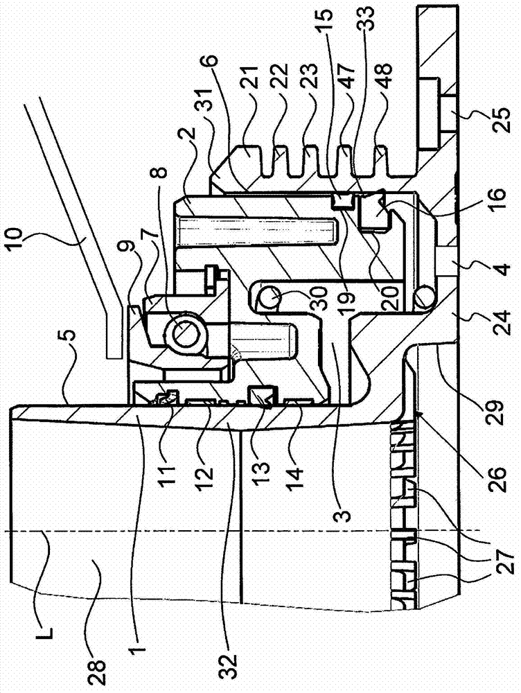
[0030] figure 1The device according to the invention is shown in section, wherein only one half of the device is shown, since the device is symmetrical and the other half, which is not shown, is configured identically.

[0031] The annular cylinder 1 can be seen with an approximately cylindrical opening 28 extending centrally in the direction of the longitudinal axis L of the annular cylinder 1 . When the annular cylinder is used as a vehicle clutch actuating device, the transmission shaft can be guided through the opening 28 . The annular cylinder 1 has a first diameter in the region of the opening 28 . In the transition region 26 , the diameter of the annular cylinder expands to a second, larger diameter until it reaches the wall 29 . The annular wall 29 serves, for example, as a receptacle for a centering flange of the transmission. thus, figure 1 The device shown can be mounted quickly and centered on the transmission. The annular cylinder 1 continues on the rear wall...


PUM


Abstract

The invention relates to a device comprising a ring cylinder (1) and a ring piston that is concentric with said ring cylinder (2), a substantially annular pressure medium chamber (3) being formed between the ring cylinder (1) and the ring piston (2). The ring piston (2) can be moved in relation to the ring cylinder (1) when pressure is applied to the pressure medium chamber (3). The invention discloses an improved embodiment of a device of this type, said device being cost-effective to produce and resistant to fatigue. To achieve this, the invention proposes that the ring cylinder (1) consists of cast aluminium and the running surfaces (5, 6) of the cylinder are anodized.

Description

technical field [0001] The invention relates to a device according to the preamble of claim 1 having an annular cylinder and an annular piston arranged concentrically on the annular cylinder. Background technique [0002] A generic device with an annular cylinder and an annular piston is known from DE 103 23 953 A1. Devices of this type are used, for example, as actuating devices for vehicle clutches. The design of such a piston / cylinder arrangement with annular piston component and cylinder component allows an advantageous space-saving installation of a clutch actuating cylinder configured in this way in the drive train of a vehicle. The annular structure allows the transmission shaft to be guided through the annular cylinder, so that the annular cylinder can be installed in a space-saving manner. [0003] It is proposed in DE 103 23 953 A1 that the piston and the cylinder are formed from sheet metal. In this case, however, it is a matter of ensuring a sufficient surface...

Claims


Application Information

Patent Timeline
IPC IPC(8): F16D25/08F16D25/12
CPCF16D2300/10F16D25/083F16D25/12F16D2300/08
Inventor 哈拉尔德·博尔歇斯斯特凡·克利克弗兰克-彼得·克卢克
Owner WABCO GMBH
Learn More