
Knitting machine with mutually differentiated control channels for the needles

A circular knitting machine, group control technology, applied in knitting, weft knitting, textiles and papermaking, etc., can solve problems such as needle and sinker damage

Inactive Publication Date: 2012-11-07
PILOTELLI MACCHINE TESSILI
View PDF9 Cites 0 Cited by
  • Summary
  • Abstract
  • Description
  • Claims
  • Application Information

AI Technical Summary

Problems solved by technology

The needle and sinker that are in contact with each other are permanently damaged and problems related to this wear occur because the sinker becomes thinner, it can also cut the yarn or can form a vertical line on the resulting stitch. Series of defects

Method used


Image

  • Knitting machine with mutually differentiated control channels for the needles
  • Knitting machine with mutually differentiated control channels for the needles
  • Knitting machine with mutually differentiated control channels for the needles

Examples


Embodiment Construction

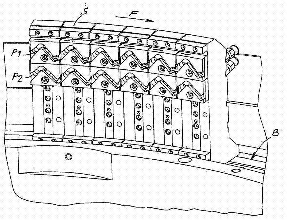
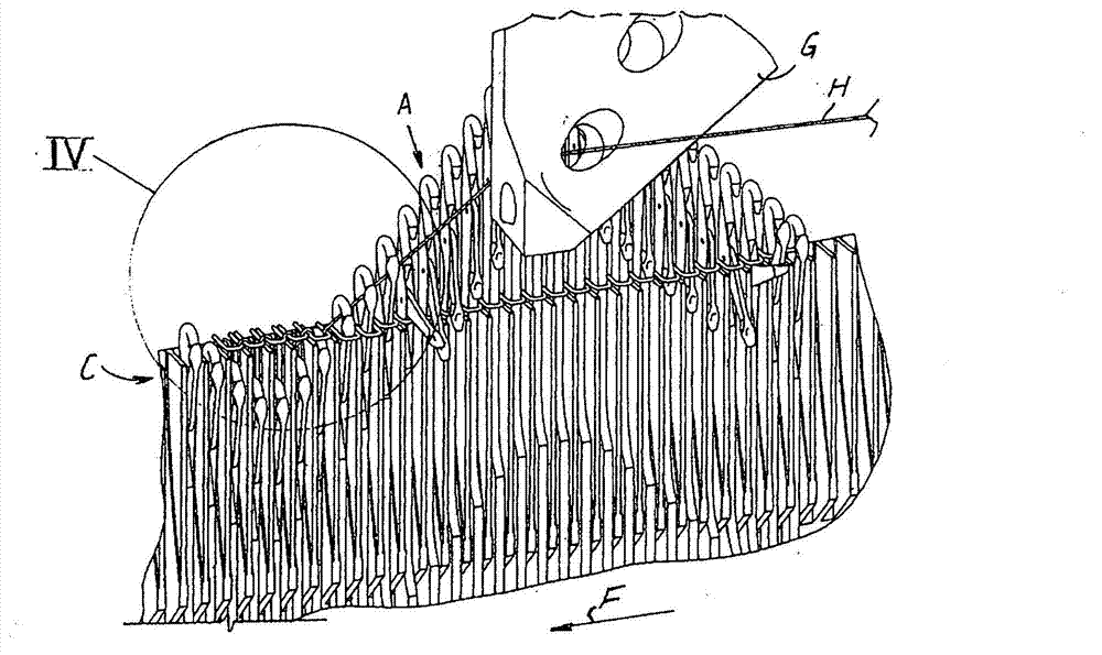
[0025] The overall structure of the knitting machine implemented by the present invention basically corresponds to the conventional machine, and it is figure 1 and 2 shown in and have been described in the previous part of the present invention.

[0026] Figure 6 The front side shows the cams used by the machine according to the invention instead of the traditional ones. More specifically, there are different types of triangles according to the invention: hereinafter referred to as "type A triangles" ( Figure 6 ) triangle defines the first needle track P1 ( figure 2 ), the triangle hereinafter referred to as "R-shaped triangle" defines the second needle path P2. exist Figure 6 Also shown in is a third type of cam, called "N-type cam", used in known machines for both needle tracks P1 and P2. still in Figure 6 Among them, F represents the rotation direction of the needle cylinder, and the vertical lines LA, LR, and LN correspond to the lowest points of the descending...


PUM


Abstract

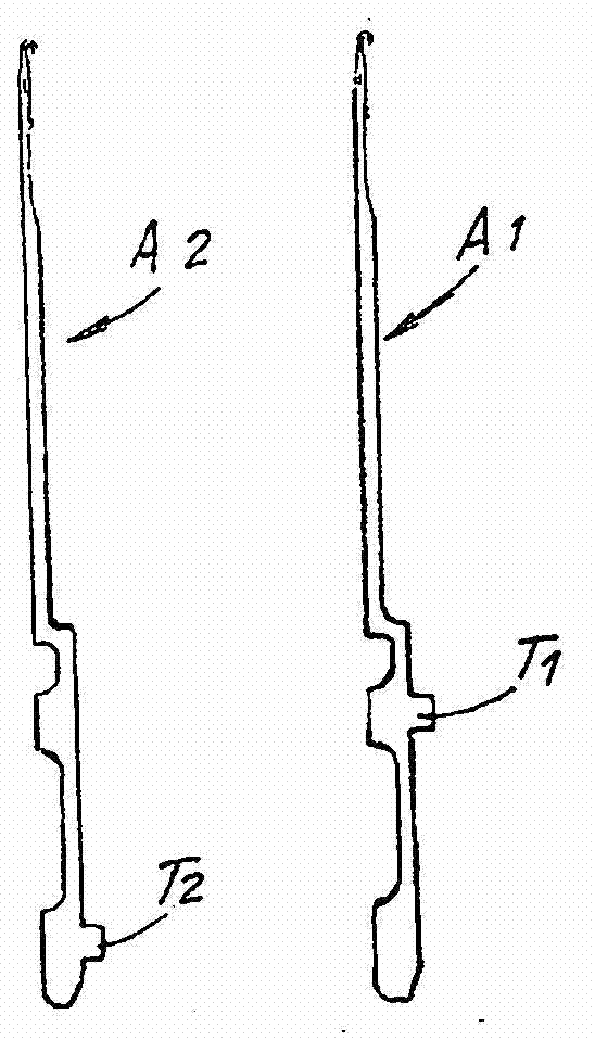
A circular knitting machine is described comprising a needle cylinder and a set of control cams for the needles that comprise ascending branches for the needles and descending branches for the needles and form at least two overlapped tracks (P1, P2) of control cams for the needles, and wherein in the needle cylinder at least two different types of needles (A1, A2) are arranged, different from each other for the different distance between butt and hook and actuated each by a respective cam track (P1, P2). The control cams (A) of a track (P1) present at least the lower part of the respective descending branch displaced in the direction of the movement of rotation of the cylinder with respect to the lower part of the respective descending branch of the corresponding cams (R) of the other track (P2), so that, on each feed, the downward movement of the needles of one type (A1) following a cam track (P1) is advanced by a preset angle of rotation of the cylinder with respect to the downward movement of the needles of the at least one other type (A2) following another cam track (P2).

Description

technical field [0001] The invention relates to the field of circular knitting machines. Background technique [0002] In known knitting machines, the stitch forming process is carried out by means of needles arranged in corresponding small guide grooves which are evenly distributed over the circumference of the rotating drum. The needles move in an alternating motion in the slots, being pulled by corresponding 'butts' actuated by a series of fixed cams (cams) mounted on dedicated cam holders surrounding the barrel. These cams have one or more slots in which the needle butt moves and which define the working path of the needle. Usually, to make a wide variety of fabric knitting patterns, a variety of needles are used, arranged on the circumference of the cylinder and differing from each other in length, ie having different distances from the butt to the hook. For each type of needle, set the corresponding triangular groove (P1, P2, figure 2 ), the triangular groove is sui...

Claims


Application Information

Patent Timeline
IPC IPC(8): D04B15/32
CPCD04B15/32D04B15/80
Inventor 雷纳托·皮洛泰利罗伯托·皮洛泰利
Owner PILOTELLI MACCHINE TESSILI
Learn More