Constant-pressure buffer distributor of printer ink pipeline
An ink tube and printer technology, applied in printing and other directions, can solve problems such as affecting picture quality, improper layout and design of ink pipelines, and increasing the instantaneous change of the flow rate of the pipeline system, so as to improve work efficiency and work performance, improve continuous Stability, the effect of continuous and stable flow
- Summary
- Abstract
- Description
- Claims
- Application Information
AI Technical Summary
Problems solved by technology
Method used
Image
Examples
Embodiment 1
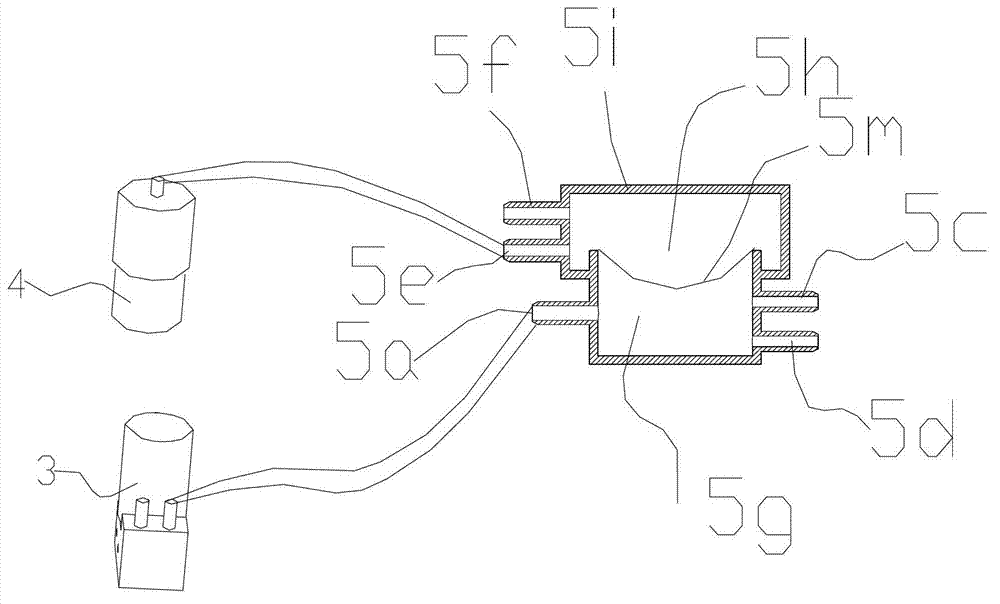
[0028] Refer to attached Figure 3-6 , Large-format printer ink pipeline constant pressure buffer distributor, including ink inlet 5a, first ink outlet 5c, second ink outlet 5d, ink buffer tank 5g and air-tight chamber 5h. A buffer film 5m is provided on the ink buffer tank 5g, and the buffer film 5m is a deformed plastic film that can protrude upwards or sag downwards on the upper surface of the ink buffer tank 5g. A layer of composite aluminum foil film 5i is also heat-sealed on the buffer tank 5g, and the buffer film 5m and the composite aluminum foil film 5i are sealed to form the air-tight chamber 5h. The air-tight cavity 5h has an air charging port 5e and an air outlet 5f. The inflation port 5e is connected with the air pump 4, and the gas outlet 5f is sequentially connected with a pressure sensor for measuring the air pressure of the air-tight chamber 5h and an air release valve.
[0029] Apply pressure to the air-tight cavity 5h by the air pump 4, the applied pressur...
Embodiment 2
[0035] The difference between this embodiment and Embodiment 1 is that the composite aluminum foil film is replaced by a plastic plate, that is, the air-tight cavity 5h on the buffer tank 5g is sealed by a plastic plate and a buffer film; the first Plastic plates are arranged on the plastic disc 5c-2, the first flow channel 5c-3, the second plastic disc 5d-2 and the second flow channel 5d-3. The first plastic disk 5c-2 and the first flow channel 5c-3, the second plastic disk 5d-2 and the second flow channel 5d-3 are respectively molded with the plastic plate at one time. Other structures and implementations of this embodiment are exactly the same as those of Embodiment 1.
Embodiment 3
[0037] The difference between this embodiment and Embodiment 1 is that the ink path constant pressure distributor described in Embodiment 1 is based on the idea of dividing the ink path into two, that is, one ink inlet and two ink outlets are provided. Through the design of the flow channel hole and the corresponding flow channel on the buffer tank, the ink path can be changed to more than one, that is, one ink inlet and more than two ink outlets. Correspondingly adjust the cross-section (hole area) of the ink inlet and ink outlet, the hole area of the ink inlet: the hole area of the ink outlet >= the number of ink outlets: the number of ink inlets, the ratio of the hole area of the general ink inlet to the outlet Not more than 3 times the ratio of the number of ink outlets to inlets. Can fully meet the ink demand of the print head.
PUM
 Abstract
Description
Claims
Application Information
 - R&D
- Intellectual Property
- Life Sciences
- Materials
- Tech Scout
- Unparalleled Data Quality
- Higher Quality Content
- 60% Fewer Hallucinations
Browse by: Latest US Patents, China's latest patents, Technical Efficacy Thesaurus, Application Domain, Technology Topic, Popular Technical Reports.
© 2025 PatSnap. All rights reserved.Legal|Privacy policy|Modern Slavery Act Transparency Statement|Sitemap|About US| Contact US: help@patsnap.com


