
Service range flow control method

A flow control and business plane technology, applied in network flow/resource management, electrical components, wireless communication, etc., can solve the problems of no flow control mechanism, user data loss, user data discarding, etc., and achieve the effect of avoiding user data loss

Inactive Publication Date: 2012-10-31
POTEVIO INFORMATION TECH
View PDF5 Cites 5 Cited by
  • Summary
  • Abstract
  • Description
  • Claims
  • Application Information

AI Technical Summary

Problems solved by technology

The user's application data is also based on UDP, so that the entire link will not have any flow control mechanism
In practical applications, since the eNodeB will serve multiple users, the air interface resources are limited, so the downlink air interface traffic (that is, the eNodeB offline egress traffic) may be smaller than the corresponding ingress traffic of the S1-U interface
If there is no flow control mechanism on the S1-U interface at this time, the user's data will be lost, which is specifically manifested as buffer overflow on the eNodeB side
[0004] It can be seen that the service plane protocol stack of the existing S1-U interface cannot guarantee the security of user data on the S1-U interface between the eNodeB and SAE-GW, which may cause user data to be discarded

Method used


Image

  • Service range flow control method
  • Service range flow control method
  • Service range flow control method

Examples


Embodiment 1

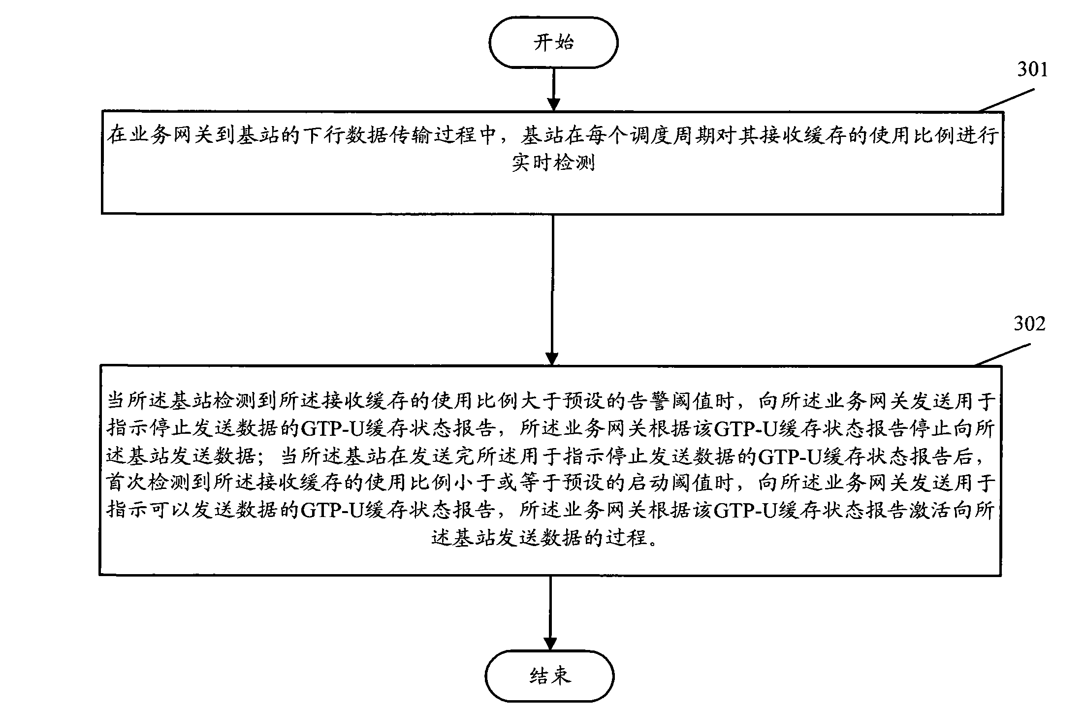
[0017] Embodiment 1 of the present invention mainly includes the following steps:

[0018] Step 301 , during the downlink data transmission process from the SAE-GW to the base station, the base station performs real-time detection of the usage ratio of its receiving buffer in each scheduling period.

[0019] Step 302, when the base station detects that the usage ratio of the receiving buffer is greater than a preset alarm threshold, send a GTP-U buffer status report to the SAE-GW indicating to stop sending data, and the SAE-GW stop sending data to the base station according to the GTP-U cache status report;

[0020] When the base station detects for the first time that the usage ratio of the receiving buffer is less than or equal to the preset startup threshold after sending the GTP-U buffer status report for instructing to stop sending data, send to the SAE-GW Sending a GTP-U buffer status report indicating that data can be sent, and the SAE-GW activates a process of sending...


PUM


Abstract

The invention provides a service range flow control method. The method includes: monitoring the size of a receiving buffer on a base station side; when occupancy of the receiving buffer achieves an alarm threshold, transmitting a GTP-U (general packet radio service tunneling protocol user plane) status report to an SAE-GW (system architecture evolution gateway) so as to inform the SAE-GW of stopping data transmission; and when the receiving buffer is idle, transmitting a GTP-U status report to the SAE-GW to inform the SAE-GW that data can be transmitted. By the service range flow control method, flow control of an S1-U interface can be effectively achieved, and the data loss of a user is avoided.

Description

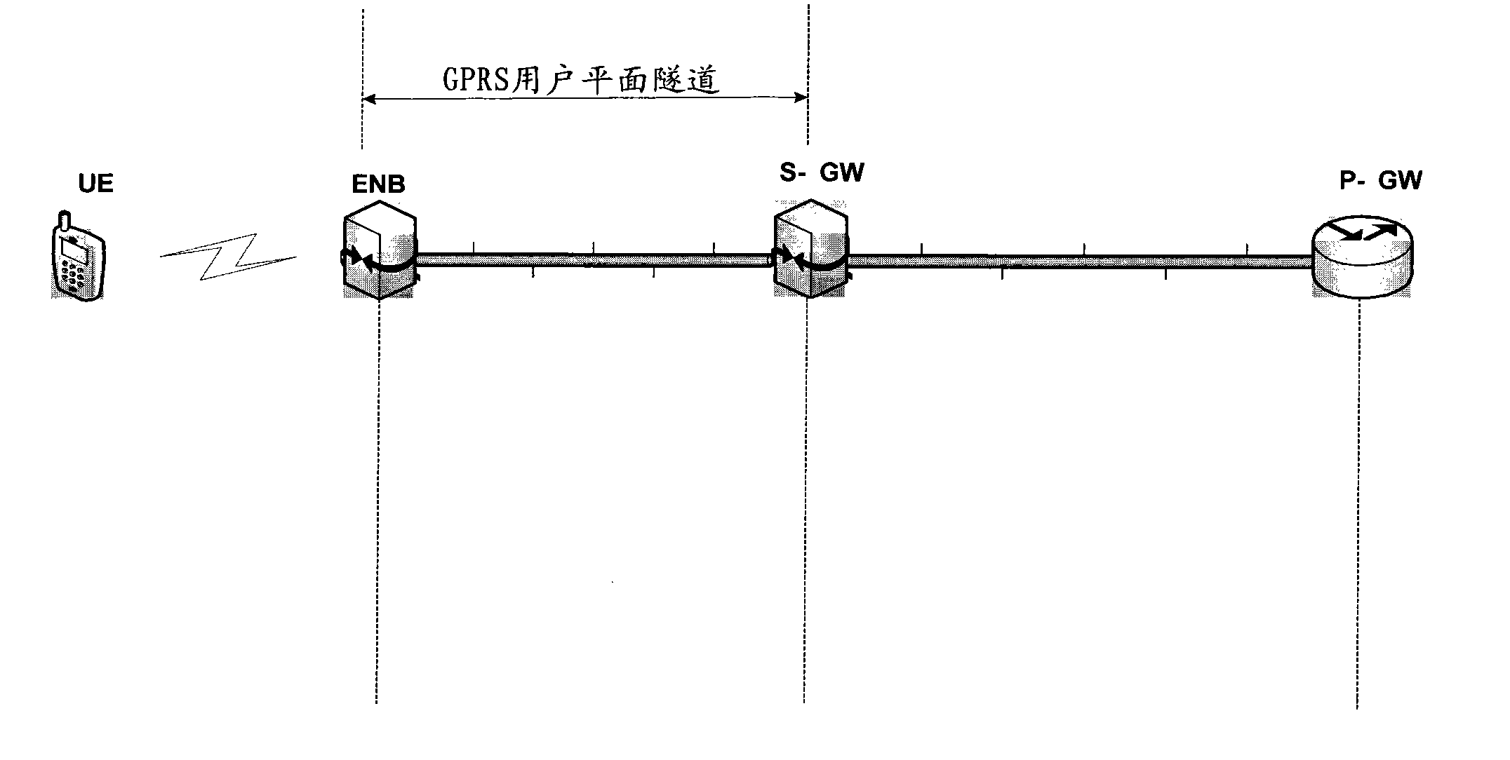
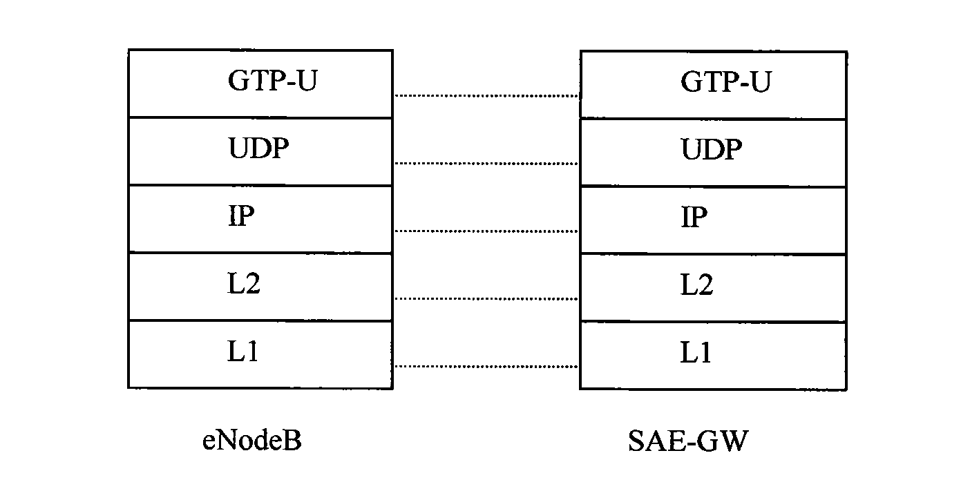
technical field [0001] The present invention relates to a flow control technology in a mobile communication system, in particular to a flow control method on a service plane between an evolved base station (eNodeB) and a system architecture evolved gateway (SAE-GW) in an LTE system. Background technique [0002] In the existing LTE and LTE-A systems, the transmission process of user data on the S1-U interface between eNodeB and SAE-GW (the following behavior examples) is as follows figure 1 shown. It can be seen from the figure that for end-to-end data transmission, in the downlink direction, the data at the user application end will pass through the public data network gateway (PDN-GW), SAE-GW, and eNodeB successively, and finally the eNodeB transmits the data through the air interface sent to the data receiver. [0003] The service plane protocol stack of the S1-U interface is as follows: figure 2 shown. from figure 2 It can be seen from the figure that the S1-U int...

Claims


Application Information

Patent Timeline
IPC IPC(8): H04W28/10
Inventor 毛加轩
Owner POTEVIO INFORMATION TECH
Learn More