
Cable Connector Assembly

A technology of cable connectors and components, applied in the direction of connection, parts of connection devices, electrical components, etc.

Inactive Publication Date: 2015-10-07
FOXCONN (KUNSHAN) COMPUTER CONNECTOR CO LTD +1
View PDF4 Cites 4 Cited by
  • Summary
  • Abstract
  • Description
  • Claims
  • Application Information

AI Technical Summary

Problems solved by technology

In the existing cable connector assembly, usually, the metal shell is completely covered by the periphery of the insulating body, so it is impossible to intuitively observe whether the connector assembly is working or not from the periphery of the cable connector assembly. Therefore, how to overcome such a problem has become a research direction for workers in the field. The following will introduce a method that can intuitively observe the cable from the periphery of the cable connector assembly. How the connector component works or not

Method used


Image

  • Cable Connector Assembly
  • Cable Connector Assembly
  • Cable Connector Assembly

Examples


Embodiment Construction

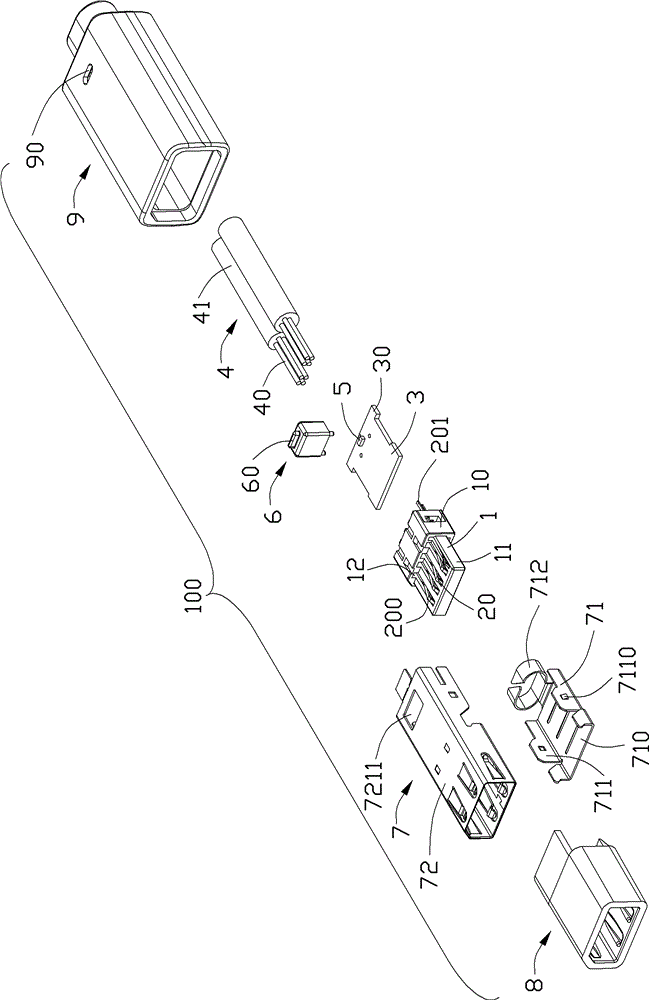
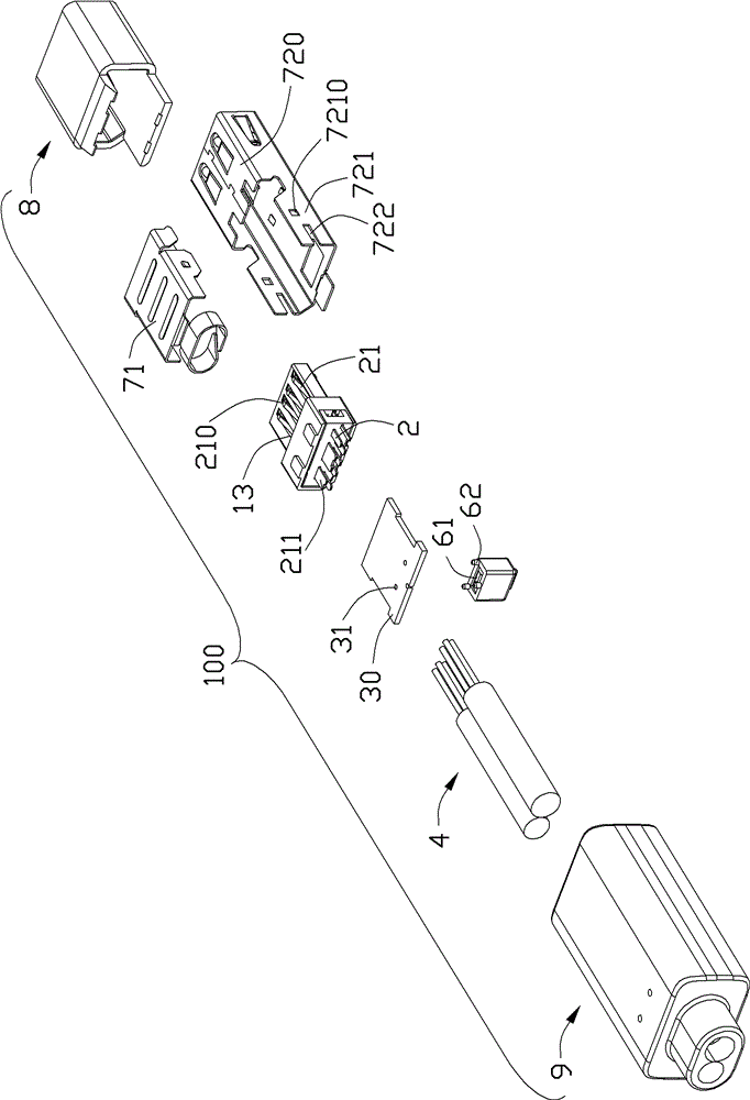
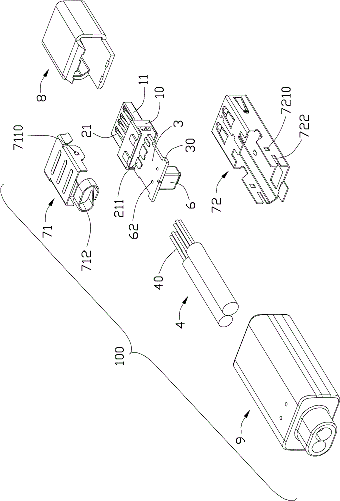
[0011] Please refer to Figure 1 to Figure 2 As shown, the cable connector assembly 100 of the present invention includes an insulating body 1, a conductive terminal 2 disposed in the insulating body 1, a printed circuit board 3 electrically connected to the conductive terminal 2, and a printed circuit board 3 electrically connected to the rear of the printed circuit board 3. The cable 4 , the LED 5 arranged above the printed circuit board 3 , the light pipe 6 arranged above the LED 5 , and the metal shell 7 covering the periphery of the insulating body 1 .

[0012] Please refer to Figure 1 to Figure 2 As shown, the insulator body 1 includes a main body 10 and a tongue 11 extending forward from the main body 10, and two rows of first holes respectively penetrating on the upper and lower surfaces of the tongue 11 are formed by recessing forward from the rear surface of the main body 10. The terminal receiving groove 12 and the second terminal receiving groove 13 . The conduc...


PUM


Abstract

The invention relates to a cable connector assembly which comprises an insulating main body, a conducting terminal contained in the insulating main body, a printed circuit board electrically connected with the conducting terminal and a metal shell shielded on the periphery of the insulating main body. The cable connector assembly also comprises an LED arranged above the printed circuit board and a light guide pipe matched with the LED, an open hole for the light guide pipe to pass through is arranged on the metal shell, and the light guide pipe passes through the open hole and extends to the periphery of the metal shell.

Description

【Technical field】 [0001] The invention relates to a cable connector assembly, in particular to a cable connector assembly capable of displaying working states. 【Background technique】 [0002] The existing cable connector assembly generally includes an insulating body, a conductive terminal disposed in the insulating body, a cable electrically connected to the conductive terminal, and a metal shell shielding the periphery of the insulating body. In the existing cable connector assembly, usually, the metal shell is completely covered by the periphery of the insulating body, so it is impossible to intuitively observe whether the connector assembly is working or not from the periphery of the cable connector assembly. Therefore, how to overcome such a problem has become a research direction for workers in the field. The following will introduce a method that can intuitively observe the cable from the periphery of the cable connector assembly. The way the connector component work...

Claims


Application Information

Patent Timeline
Patent Type & Authority Patents(China)
IPC IPC(8): H01R13/717H01R13/502
Inventor 周毅陈峰杨忠晏马迎星柯作锦邢大伟
Owner FOXCONN (KUNSHAN) COMPUTER CONNECTOR CO LTD
Learn More