Piezoelectric transformer drive circuit
A piezoelectric transformer and drive circuit technology, which is applied to instruments, electric light sources, electrical components, etc., can solve the problems of large differences in piezoelectric transformers, increased difficulty of miniaturization, increased manufacturing costs, etc., and achieves low flickering and current balance better performance and improved current balance
- Summary
- Abstract
- Description
- Claims
- Application Information
AI Technical Summary
Problems solved by technology
Method used
Image
Examples
Embodiment 1
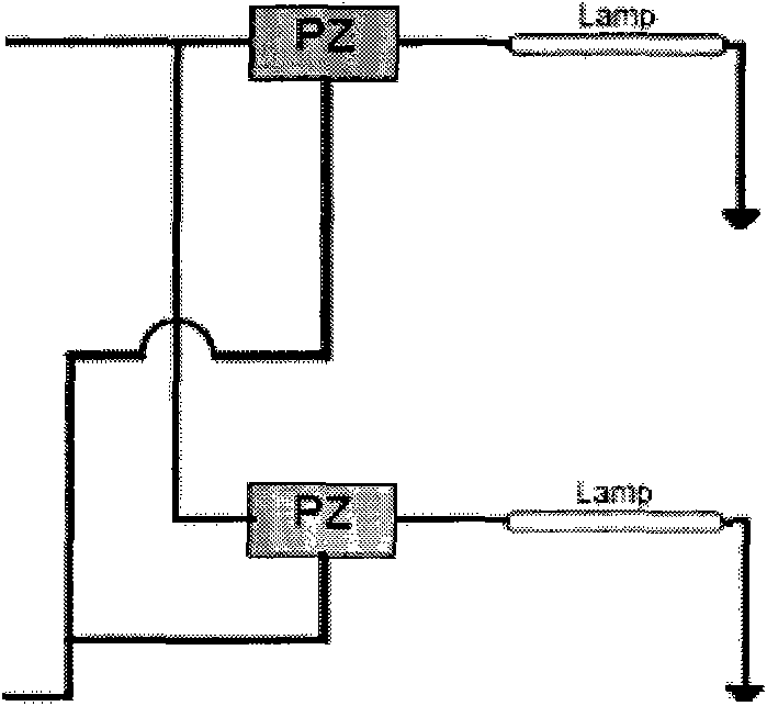
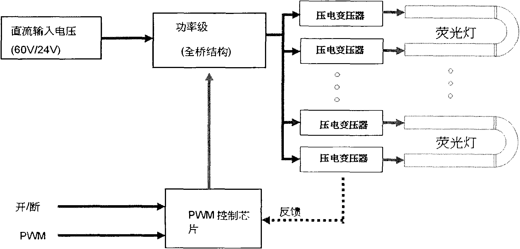
[0024] figure 2 A logical block diagram showing a piezoelectric transformer drive circuit according to the first embodiment of the present invention; as figure 2 As shown, the driving circuit includes an input voltage module, a power stage module, a piezoelectric transformer group, a fluorescent lamp group, a PWM control chip and a switch circuit. Wherein, the input voltage module is connected with the power stage module, and is used for supplying the input DC voltage to the power stage module. Wherein, the power stage module is a full bridge structure circuit. Wherein, the power stage module is connected with the piezoelectric transformer group, and two adjacent piezoelectric transformers are used to drive a fluorescent lamp. Wherein, the terminals on the primary side of the piezoelectric transformer group are connected in series, and the bottom terminal is connected to a PWM control chip, and the PWM control chip adjusts the current input of the full bridge structure acc...
Embodiment 2
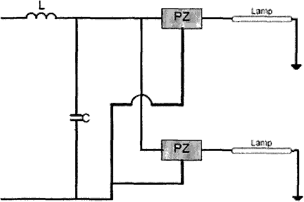
[0028] image 3 shows a piezoelectric transformer drive circuit according to a second embodiment of the present invention, image 3 lieutenant general and figure 2 Similar parts are omitted, while referring to figure 2 and image 3 , The piezoelectric transformer driving circuit of the second embodiment includes the driving circuit including an input voltage module, a power stage module, a piezoelectric transformer group, a fluorescent lamp group, a PWM control chip, a resonant circuit and a switch circuit. Wherein, the input voltage module is connected with the power stage module, and is used for supplying the input DC voltage to the power stage module. Wherein, the power stage module is a full bridge structure circuit. Wherein, the power stage module is connected with the resonant circuit, the full bridge circuit is switched to generate a square wave signal, the square wave signal is converted into a sine wave signal by the resonant circuit, and the sine wave signal is...
Embodiment 3
[0034] Figure 5 A logical block diagram showing a piezoelectric transformer driving circuit according to a third embodiment of the present invention; as Figure 5 As shown, the driving circuit includes an input voltage module, a power stage module, a resonant circuit, a piezoelectric transformer group, a fluorescent lamp group, a PWM control chip and a switch circuit.
[0035] Wherein, the input voltage module is connected with the power stage module, and is used for supplying the input DC voltage to the power stage module. Wherein, the power stage module is a full bridge structure circuit. Wherein, the power stage module is connected with the resonant circuit, the full bridge circuit is switched to generate a square wave signal, the square wave signal is converted into a sine wave signal by the resonant circuit, and the sine wave signal is provided to the piezoelectric transformer. Two adjacent piezoelectric transformers are used to drive a fluorescent lamp. Wherein, the ...
PUM
 Abstract
Description
Claims
Application Information
 - Generate Ideas
- Intellectual Property
- Life Sciences
- Materials
- Tech Scout
- Unparalleled Data Quality
- Higher Quality Content
- 60% Fewer Hallucinations
Browse by: Latest US Patents, China's latest patents, Technical Efficacy Thesaurus, Application Domain, Technology Topic, Popular Technical Reports.
© 2025 PatSnap. All rights reserved.Legal|Privacy policy|Modern Slavery Act Transparency Statement|Sitemap|About US| Contact US: help@patsnap.com


