
A light bar, a light bar structure and a light bar packaging structure

A packaging structure and light bar technology, applied in lighting devices, lighting device parts, lighting and heating equipment, etc., can solve the problems of no protection mechanism, impact, high defect rate, etc. The effect of packaging efficiency and high adaptability

Inactive Publication Date: 2012-10-31
LEXTAR ELECTRONICS CORP
View PDF6 Cites 2 Cited by
  • Summary
  • Abstract
  • Description
  • Claims
  • Application Information

AI Technical Summary

Problems solved by technology

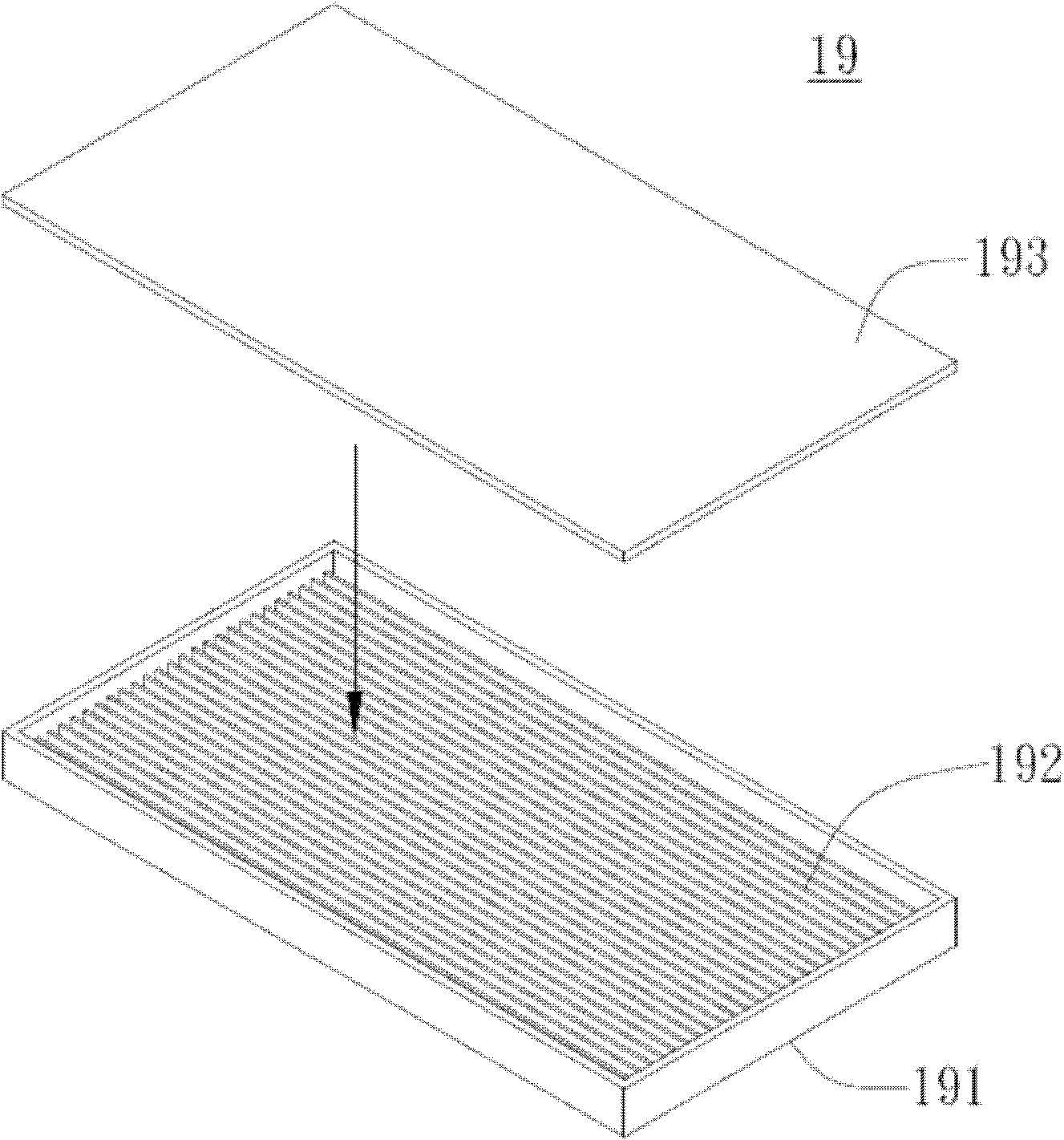
If a shorter light bar is placed on the packaging structure 19, the light bar cannot be completely fixed, so that the light bar is easy to shake
As for the protection of the light bar, the light bar is easy to slide or be hit, and there is no corresponding protection mechanism during transportation
Furthermore, since the packaging structure is of a fixed shape, often when the light bar is filled, there is still a lot of idle space in the packaging structure, so the space cannot be fully utilized.
[0005] Specifically, the traditional light bar has a long strip-shaped four-sided flat structure, so the assembly can only be assisted by manual positioning, which is likely to cause a high defect rate
In addition, the packaging structure of the light bar has an unchangeable structural shape, and there are still many idle spaces after being filled with light bars of different specifications
Therefore, no matter the traditional lamp bar or the packaging structure of the lamp bar, there are the above-mentioned disadvantages

Method used


Image

  • A light bar, a light bar structure and a light bar packaging structure
  • A light bar, a light bar structure and a light bar packaging structure
  • A light bar, a light bar structure and a light bar packaging structure

Examples


Embodiment Construction

[0060] The present invention will be further described below in conjunction with the accompanying drawings.

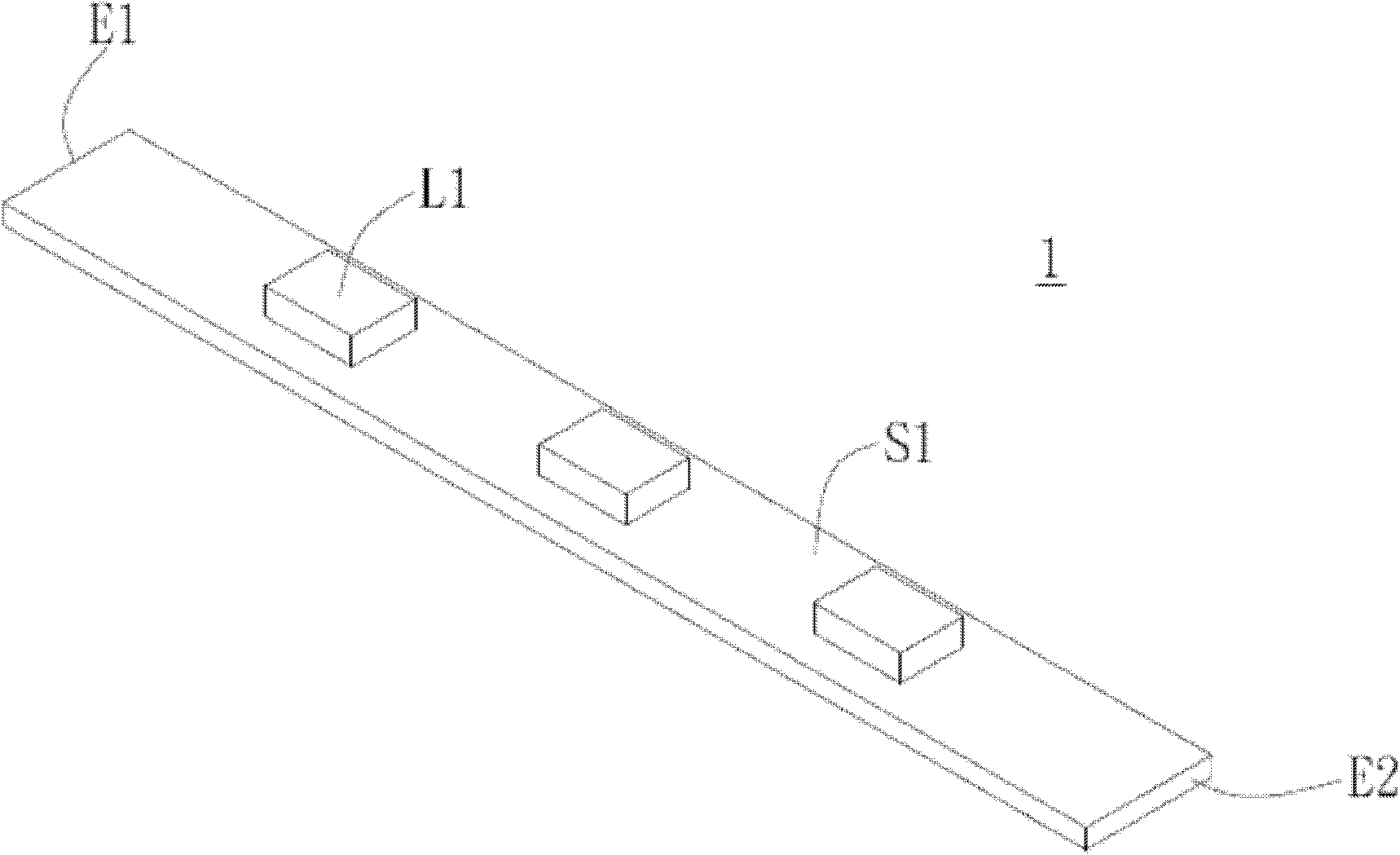
[0061] A specific embodiment of the invention is a light bar. In this embodiment, the light bar may be an LED light bar, but it is not limited thereto, and there is no specific limitation.

[0062] refer to figure 2 , figure 2 It is a top view of an embodiment of the light bar of the present invention. like figure 2 As shown, the light bar 1 includes a first substrate 15 , several light sources 16 , a first engaging portion 131 and a second engaging portion 132 . The first substrate 15 has a first edge 111 and a second edge 112 . The light source 16 is disposed on the first substrate 15 along the line connecting the first edge 111 and the second edge 112 . In this embodiment, the light source 16 is preferably a light emitting diode.

[0063] It should be noted that the first engaging portion 131 is disposed on the first end edge 111 and is recessed toward the...


PUM


Abstract

The invention provides a light bar and a light bar packaging structure. The light bar comprises a first substrate, a plurality of light sources, a first snap fit part, and a second snap fit part, wherein the first substrate comprises a first end edge and a second end edge, the light sources are disposed on the first substrate along the direction of the connecting line of the first end edge and the second end edge, the first snap fit part is disposed on the first end edge and is sunk towards the second end edge, the second snap fit part disposed on the second end edge and is sunk towards the first end edge, the first snap fit part comprises a first arm plate and a second plate which extend towards the direction of the outer side of the first end edge and disposed on the two sides of the sunk part, the second snap fit part comprises a third arm plate and a fourth arm plate which extend towards the direction of the outer side of the second end edge and disposed on the two sides of the sunk part. The invention provides the light bar, a light bar structure comprising the light bar and the light bar packaging structure which is capable of protecting the light bar, improving the packaging efficiency and improving convenience and packaging efficiency during assembly.

Description

technical field [0001] The invention relates to a light bar, a light bar structure and a packaging structure containing the light bar; in particular, the invention relates to a light bar packaging structure capable of protecting the light bar and improving packaging efficiency. Background technique [0002] With the development of science and technology, the optoelectronic industry continues to develop more energy-saving and brighter lighting sources. For example, the light bar is the most common lighting source at present. It has many advantages such as power saving and low heat generation. It has gradually replaced traditional lighting devices and is widely used in various fields, such as flashlights, desk lamps, monitors, and advertising billboards. And the exterior walls of buildings, light bars can be seen everywhere, which have penetrated into the lives of modern people. However, the application of modern technology is varied. How to make the most of the light bar and...

Claims


Application Information

Patent Timeline
Patent Type & Authority Applications(China)
IPC IPC(8): F21S4/00F21V19/00F21V17/00F21S4/28
Inventor 刘雷馨陈俊光
Owner LEXTAR ELECTRONICS CORP
Learn More