Electric fuel pump

An electric fuel pump and pump chamber technology, which is applied in the field of fuel pressurization devices, can solve the problems of hindering work, not getting flow and pressure, and the oil pump is difficult to work normally, so as to achieve the effect of uniform friction and prolonging the service life

Inactive Publication Date: 2012-10-31
孙立生 +1
View PDF8 Cites 0 Cited by
  • Summary
  • Abstract
  • Description
  • Claims
  • Application Information

AI Technical Summary

Problems solved by technology

However, he may not have considered that two sets of blades with different radii on one impeller correspond to two oil grooves with different radii, and the linear speeds of the blades in the inner and outer grooves are inconsistent, so the outer oil groove will drag the fluid in the inner oil groove , the inner oil tank will hinder the work instead, making it difficult for the oil pump to work normally, and it will not get the expected flow and pressure
This kind of fuel pump has not been seen in the market so far

Method used


Image

  • Electric fuel pump
  • Electric fuel pump
  • Electric fuel pump

Examples


Embodiment 1

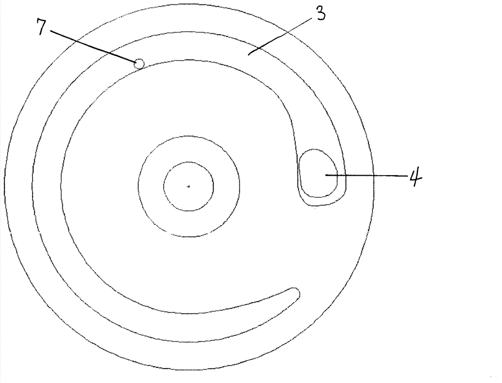
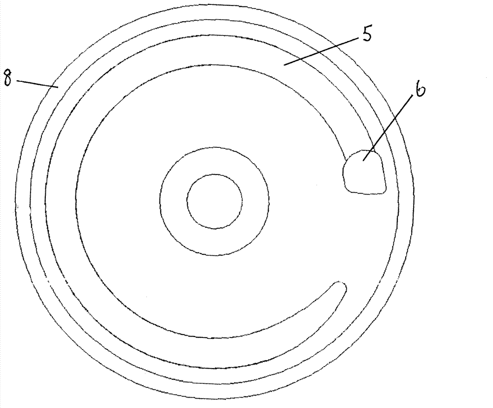
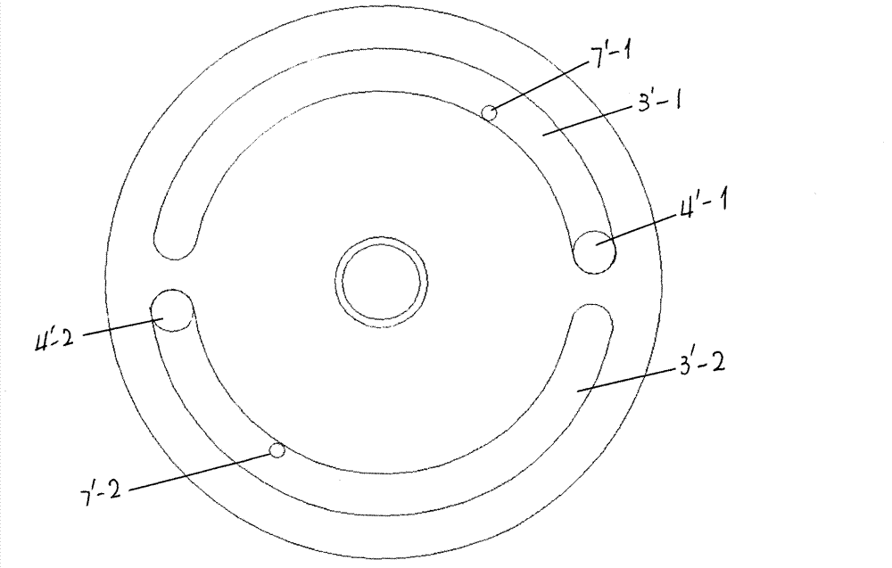
[0018] An electric fuel pump, which includes a circular pump chamber, the pump chamber is composed of two shells and an impeller, the lower shell 1' is a circular flat plate, and the upper shell 2' has a circle of protrusions around it The shoulder is 8' and the shoulder height is 4mm, forming a circular box shape, which matches the impeller, and the impeller is seated in it. Sheet 2' caps are tightly sealed to form pump chambers such as image 3 and 4 As shown, there are two concave arc-shaped first oil inlet grooves 3'-1 and second oil inlet grooves 3'-2 connected end to end and concentric with the casing on the inner bottom surface of the lower part 1' of the casing. The arc length of each oil inlet groove 3' is 175 degrees. 'The first oil inlet hole 4'-1 and the second oil inlet hole 4'-2, the tail ends of the first oil inlet groove 3'-1 and the second oil inlet groove 3'-2 gradually become shallow and terminate. An oil inlet groove 3'-1 has a first drain hole 7'-1 pene...


PUM


Abstract

An electric fuel pump comprises a pump chamber, wherein an upper shell plate and a lower shell plate of the pump chamber are respectively provided with two fuel intake grooves and fuel discharge grooves which have centrosymmetric planes having radian of 170-175 DEG; when the fuel is pumped by a fuel pump impeller, the reverse thrust acting forces applied to a fuel outlet during fuel injection are symmetrically balanced, and the flow and the work pressure are increased. The electric fuel pump overcomes an inherent problem that a fuel pump with an annular single fuel channel in the prior art is easily worn.

Description

technical field [0001] The invention relates to an electric fuel pump used in a motor vehicle, which is mainly used in a fuel supply system of an electric injection engine, and is a fuel pressurizing device. Background technique [0002] Electric fuel pumps for motor vehicles, mainly for gasoline, methanol or ethanol and such mixed fuels including all liquid fuel engines. The basic structure of the current electric fuel pump has been formed. It includes a circular pump chamber. The pump chamber is composed of two shells and an impeller. The lower shell 1 is a circular flat plate, and the upper shell 2 is surrounded by There is a circle of raised shoulders 8, forming a circular box shape, which matches the impeller, the impeller is seated in it, the lower shell 1 can be closed on the shoulder of the upper shell 2, and the upper shell 2 is covered. It is tightly sealed to form a pump chamber. On the inner bottom surface of the lower part 1 of the casing, there is a concave ar...

Claims


Application Information

Patent Timeline
Patent Type & Authority Applications(China)
IPC IPC(8): F04D29/42
CPCF04D5/007
Inventor 孙立生孙平平
Owner 孙立生
Why Eureka
Try Eureka