Brake system
A brake system and brake cylinder technology, applied in the direction of brake control systems, brakes, brake components, etc.
- Summary
- Abstract
- Description
- Claims
- Application Information
AI Technical Summary
Problems solved by technology
Method used
Image

Examples
Embodiment 1
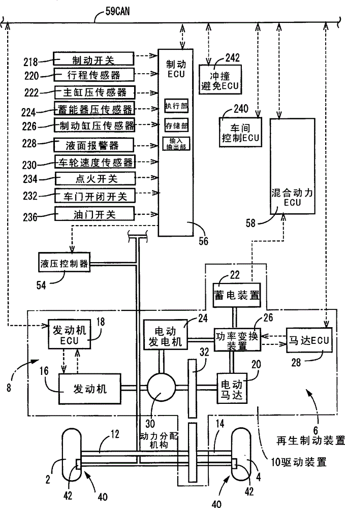
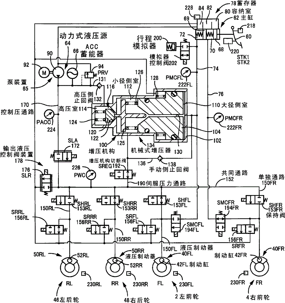
[0152] The hydraulic brake system involved in Embodiment 1 includes figure 2 brake circuit shown.
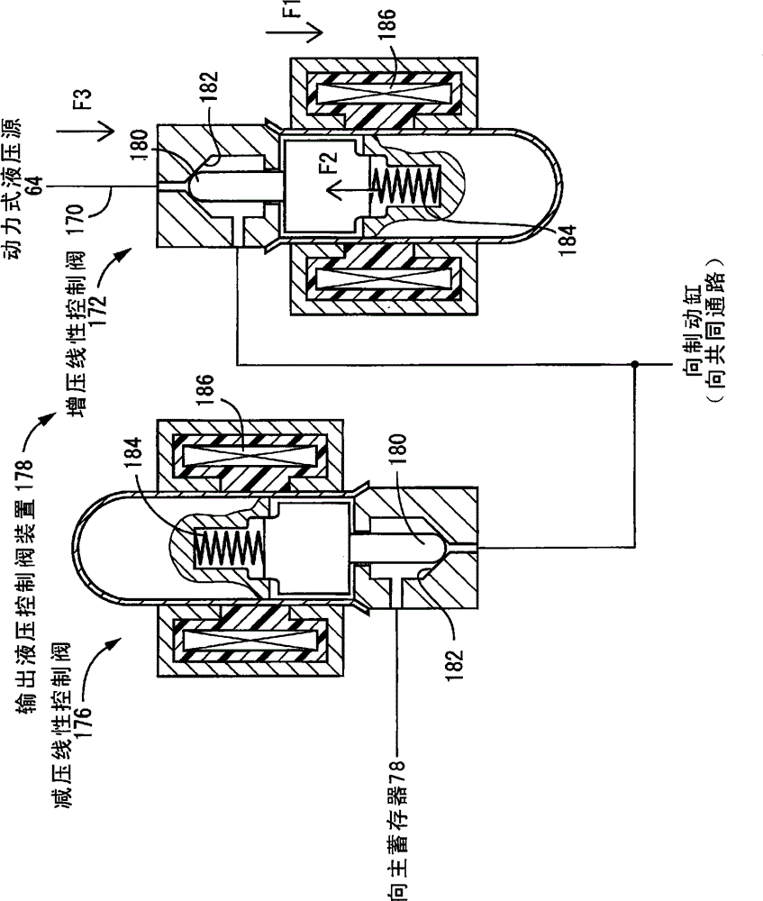
[0153] Reference numeral 60 is a brake pedal serving as a brake operating member, and reference numeral 62 is a master cylinder serving as a manual hydraulic pressure source that generates hydraulic pressure when the brake pedal 60 is operated. Reference numeral 64 is a power hydraulic source including a pump device 65 and an accumulator 66 . The hydraulic brakes 40, 50 are operated by the hydraulic pressure of the brake cylinders 42, 52 to restrain the rotation of the wheels, which in this embodiment are disc brakes.
[0154] The hydraulic brakes 40, 50 may be drum brakes. In addition, the hydraulic brakes 40 of the front wheels 2 and 4 may be disc brakes, and the hydraulic brakes 50 of the rear wheels 46 and 48 may be drum brakes.
[0155] The master cylinder 62 is a tandem hydraulic cylinder including two pressurizing pistons 68 , 69 , and the respective fronts of the pre...
Embodiment 2
[0263] Figure 9 The brake circuit of the hydraulic brake system of Embodiment 2 is shown. Components that are the same as those of the brake circuit in Embodiment 1 are denoted by the same symbols and descriptions thereof are omitted. In addition, the control and the like performed by the brake ECU 56 are the same as those in Embodiment 1.
[0264] In Embodiment 2, the common passage 310 is connected to the brake cylinders 52RL, RR of the left and right rear wheels 46, 48 via a single passage 312 . The hydraulic pressures of the brake cylinders 52RL, RR of the left and right rear wheels 46, 48 are commonly controlled. Also, a common holding valve 314 is provided in the individual passages 312 . The holding valve 314 is a normally closed electromagnetic on-off valve. In addition, a brake cylinder side check valve 316 is provided in parallel with the holding valve 314 , and the brake cylinder side check valve 316 allows hydraulic fluid to flow from the brake cylinders 52RL,...
Embodiment 3
[0288] In the hydraulic brake system of Embodiment 2, when the possibility of fluid leakage is detected, set Figure 12 states shown, but not limited to.
[0289] Next, control of the left and right shutoff valves 332 and the front and rear shutoff valves 330 when a possibility of fluid leakage is detected in the brake system including the hydraulic brake circuit described in the second embodiment will be described.
[0290] When the possibility of liquid leakage is detected, it is desirable to keep the left and right shutoff valves 332 and the front and rear shutoff valves 330 in the closed state as much as possible. Even if the possibility of fluid leakage is detected, it may not necessarily be that there is actually a fluid leakage, but if there is an actual fluid leakage, it is desirable to prevent the influence of the fluid leakage from affecting other brake lines. However, the left and right shutoff valves 332 and the front and rear shutoff valves 330 are electromagneti...
PUM
 Abstract
Description
Claims
Application Information
 - R&D
- Intellectual Property
- Life Sciences
- Materials
- Tech Scout
- Unparalleled Data Quality
- Higher Quality Content
- 60% Fewer Hallucinations
Browse by: Latest US Patents, China's latest patents, Technical Efficacy Thesaurus, Application Domain, Technology Topic, Popular Technical Reports.
© 2025 PatSnap. All rights reserved.Legal|Privacy policy|Modern Slavery Act Transparency Statement|Sitemap|About US| Contact US: help@patsnap.com