
Precision fluid dispensing device

a fluid dispensing device and precision technology, applied in the direction of positive displacement liquid engine, piston pump, packaging, etc., can solve the problems of inaccurate dose volume, high maintenance requirements, high upfront capital and maintenance costs, etc., and achieve the effect of accurate dispense of solution, low cost, and fast delivery method

Active Publication Date: 2022-04-05
HARTMANNS INC +1
View PDF14 Cites 0 Cited by
  • Summary
  • Abstract
  • Description
  • Claims
  • Application Information

AI Technical Summary

Benefits of technology

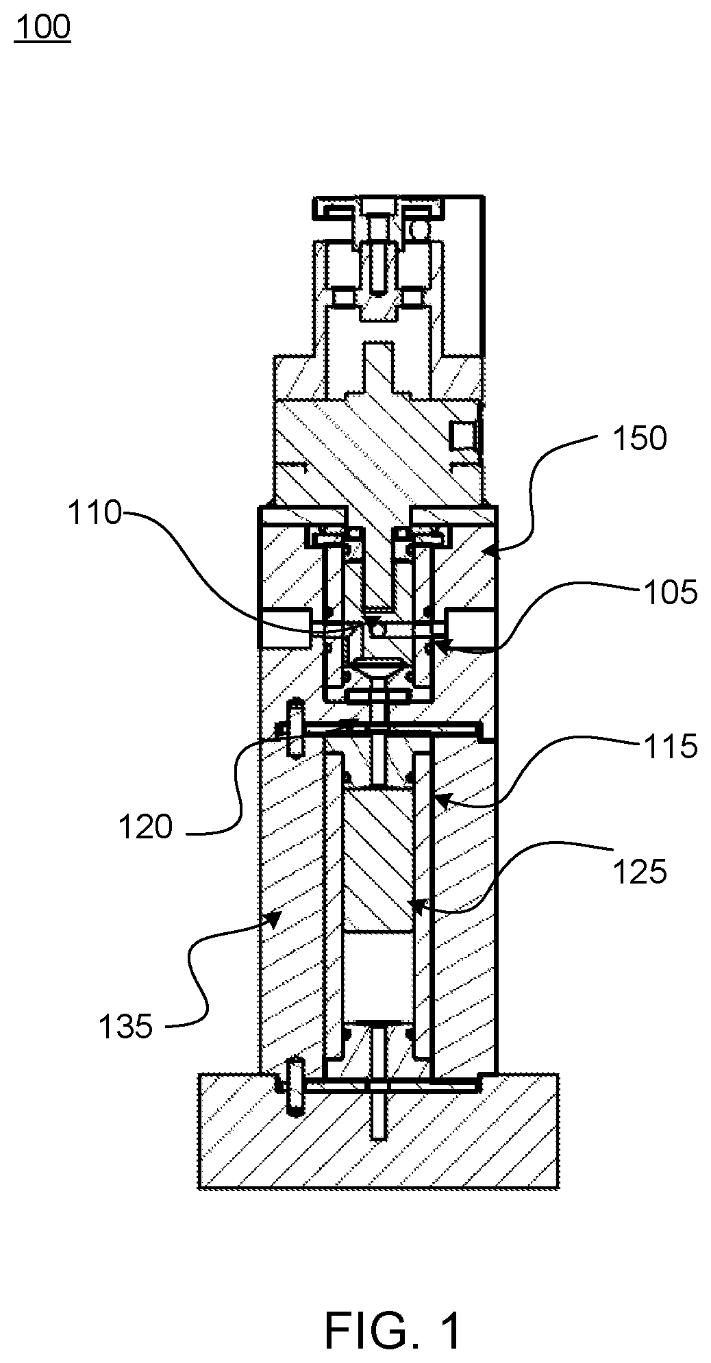
[0011]What is needed is a single stroke piston with a pressurized fluid supply to provide the least invasive manipulation of fluid with a fast delivery method to the nozzle. A pneumatic rotary motion or electrical solenoid valve may be incorporated to direct the fluid to and from alternating sides of the piston. No adjustment may be needed by an end user since there is a fixed volume as a result of the geometry of the components. This may provide a simpler way to very accurately dispense a solution while minimizing the complexity of the other systems available on the market. Combining simplicity with something like a fixed length ceramic piston may eliminate many of the components used in other systems that may cause failure in the equipment.
[0012]This single stroke piston can dispense a very accurate volume of fluid using the head pressure of the fluid in an elevated reservoir or a pressurized fluid supply method. Without check valves, the dispensing device may dispense gently and very quickly. The dispenser may dose and fill at the same time, making a dose as fast as liquid can fill a chamber. The velocity of the discharged fluid is dependent on the nozzle diameter, or by means of a flow control valve. Parts may be autoclave capable for use in a variety of industries that require sanitation. Since some of the parts may be inert, the device can accommodate a variety of fluids currently used in industry. The potential for leakage is minimal as the fluid path is completely enclosed. Users can convert to other dose volumes by simply changing one component of the device. A single moving part minimizes risk of fluid contamination due to debris.

Problems solved by technology

For example, microprocessor-controlled syringe pumps can offer precision and speed but expensive upfront capital and maintenance costs, while peristaltic pumps may reduce back flushing but have high maintenance requirements.
This adjustment requires much time for multiple extrapolation trial measurements and commonly leads to incorrect dose volume due to human error.
Each of these types of pumps has their limitations.
For example, the peristaltic pump has low accuracy and low repeatability.
They typically require a lot of maintenance with an accompanying high cost and interruption of operation.
Diaphragm pumps are also not very accurate and tend to be slow.
They are also susceptible to wear and fluid contamination.
The diaphragms themselves can fail and leak fluid, while the check valves can also fail frequently depending on fluid type and temperature.
Piston pumps are accurate, but slow, since the piston has to retract to charge the next dose depending on the valve used.
The valves often fail or do not integrate with certain liquids.
Metering pumps have high accuracy and repeatability, but require great expense to maintain and require knowledge of the technical controls since most are programmable and motor driven.
All of these options are expensive, difficult to maintain, and not as accurate as they have the potential to be.
Parts and components constantly fail and it is difficult to pinpoint exactly what goes wrong when the complete system is too complex for some production environments.
Most are high risk for fluid contamination as they wear.

Method used


Image

  • Precision fluid dispensing device
  • Precision fluid dispensing device
  • Precision fluid dispensing device

Examples


Embodiment Construction

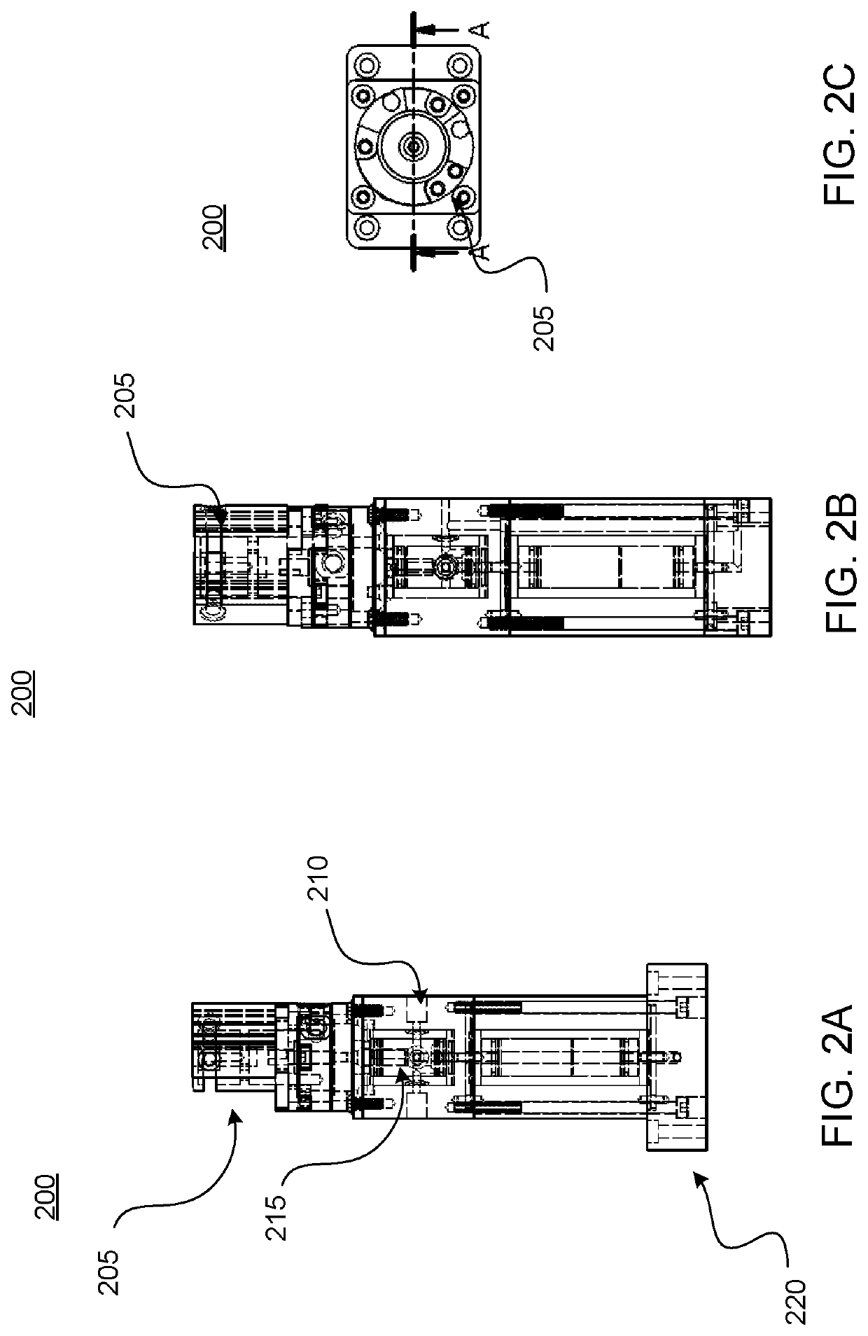
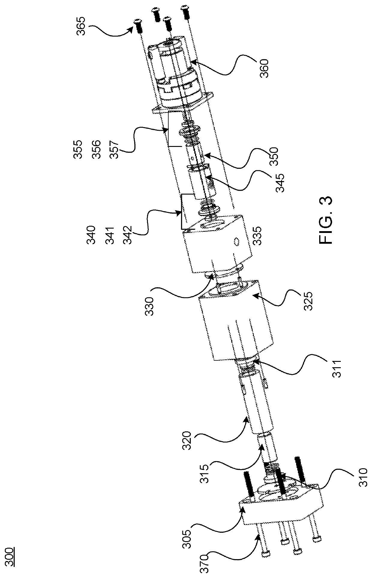
[0036]The present disclosure provides generally for a fluid-dispensing device. More specifically, the present disclosure provides for a precision fluid-dispensing device that may deliver a predefined volume of fluid quickly and reliably. In some aspects, the precision fluid-dispensing device may be used to deliver a fluid to a receiving container, such as in a manufacturing line, as a non-limiting example.

[0037]In some embodiments, the precision fluid-dispensing device may dispense very accurate volumes of fluid using the head pressure of the fluid from an elevated reservoir or fluid supply pressurized by other means. In some aspects, the precision fluid-dispensing device may not comprise check valves, which may allow for more frequent use with limited need for adjustments and maintenance due to component wear and failure. In some implementations, the precision fluid-dispensing device may dispense fluid gently and quickly, which may allow for handling of fluids that may be sensitive...


PUM


Abstract

The present disclosure provides generally for a fluid-dispensing device. More specifically, the present disclosure provides for a precision fluid-dispensing device that may deliver a predefined volume of fluid quickly and reliably. In some aspects, the precision fluid-dispensing device may be used to deliver a fluid to a receiving container, such as in a manufacturing line, as a non-limiting example. In some embodiments, the precision fluid-dispensing device may dispense very accurate volumes of fluid using the head pressure of the fluid from an elevated reservoir or pressurized fluid supply. In some implementations, the precision fluid-dispensing device may dispense fluid gently and quickly, which may allow for handling of fluids that may be sensitive to agitation or mixing.

Description

CROSS-REFERENCE TO RELATED APPLICATION[0001]This application claims priority to and the full benefit of U.S. Provisional Patent Application Ser. No. 62 / 561,269, filed Sep. 21, 2017, and titled “PRECISION FLUID DISPENSING DEVICE”, the entire contents of which are incorporated in this application by reference.BACKGROUND OF THE DISCLOSURE[0002]Dispensing systems can deliver precise amounts of fluid in the microliter, or milliliter range. These systems may be used in general manufacturing, pharmaceutical, printing, mixing, drug discovery, materials science, food safety, and forensics. There are a range of possible variations available, including manual or automatic dispensers and designs ranging from single to multi-channel systems. Each design may have tradeoffs. For example, microprocessor-controlled syringe pumps can offer precision and speed but expensive upfront capital and maintenance costs, while peristaltic pumps may reduce back flushing but have high maintenance requirements. S...

Claims


Application Information

Patent Timeline
Patent Type & Authority Patents(United States)
IPC IPC(8): B65D83/00F04B1/00F04B7/06F04B13/00
CPCF04B1/00B65D83/0005F04B7/06F04B13/00
Inventor HARTMANN, MICHAEL ALANDUNCAN, DAVID
Owner HARTMANNS INC
Learn More