
Control method, device and computer system for data transmission

A control method and a technology of a control device, which are applied in the field of communication, can solve the problems of unfavorable data transmission and effective utilization of bandwidth, network transmission speed reduction, and large control lag.

Active Publication Date: 2012-10-24
HUAWEI TECH CO LTD
View PDF3 Cites 11 Cited by
  • Summary
  • Abstract
  • Description
  • Claims
  • Application Information

AI Technical Summary

Problems solved by technology

[0007] First: According to the ACK message fed back by the receiving end, the prior art network sending device estimates whether the data of this connection is lost and whether the delay exceeds the predetermined range through the determination signal in the ACK message. However, the network transmission itself has a delay, which is likely The data that has not received the ACK feedback signal is currently in the network transmission and will effectively arrive at the receiving end after a certain period of time; when the sending end does not receive the ACK feedback message of the data within the predetermined time, it will determine that the data is lost Congestion control is activated due to packet loss, which leads to a significant drop in network transmission speed due to misjudgment of the occurrence of packet loss in the network, which is not conducive to data transmission and effective use of bandwidth.
[0008] Second: In particular, in the long-fat pipeline network with a large network transmission delay, due to the large delay in network transmission, the sending end is likely to keep most of the data still in transmission according to the ACK message fed back by the receiving end. The data in the process is misjudged as unsuccessfully sent data, resulting in a high misjudgment of packet loss rate, and the above-mentioned transmission speed control will cause data transmission in the network to exist due to sporadic packet loss or misjudgment of packet loss rate. Large shock, which affects the sending of data
[0009] Third: The congestion control in the prior art is to control the transmission of the next control cycle according to the ACK feedback confirmation information of the receiving end, and its control has a large hysteresis
Moreover, in the network, there may be new users joining at any time, and the control method of the above-mentioned scheme 1 is not suitable for a network that changes at any time, and its applicable flexibility is poor
[0010] In fact, a certain user in the network currently has no data transmission service, and the existing technical solutions cannot dynamically use the current idle bandwidth for the user to improve the data service transmission efficiency of each current connection according to the current network status changes

Method used


Image

  • Control method, device and computer system for data transmission
  • Control method, device and computer system for data transmission
  • Control method, device and computer system for data transmission

Examples


Embodiment 1

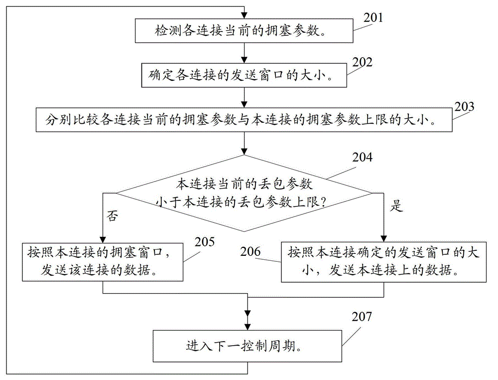
[0050] This embodiment provides a method for controlling data transmission, and the method is applicable to the data transmission control of each network transmission device in the network. see figure 2 As shown, the data transmission control method in this embodiment mainly includes the following steps:

[0051] Step 201: Detect the current congestion parameters of each connection.

[0052] In this embodiment, the network transmission device or the control device connected to the network transmission device can detect in real time the packet loss situation of each current connection of the network transmission device and parameters reflecting the congestion situation of the connection such as time delay to determine the current status of each connection. Congestion parameters.

[0053] Step 202: Determine the size of the sending window of each connection.

[0054] In data sending, the network sending device limits the actual amount of data sent within a predetermined cont...

Embodiment 2

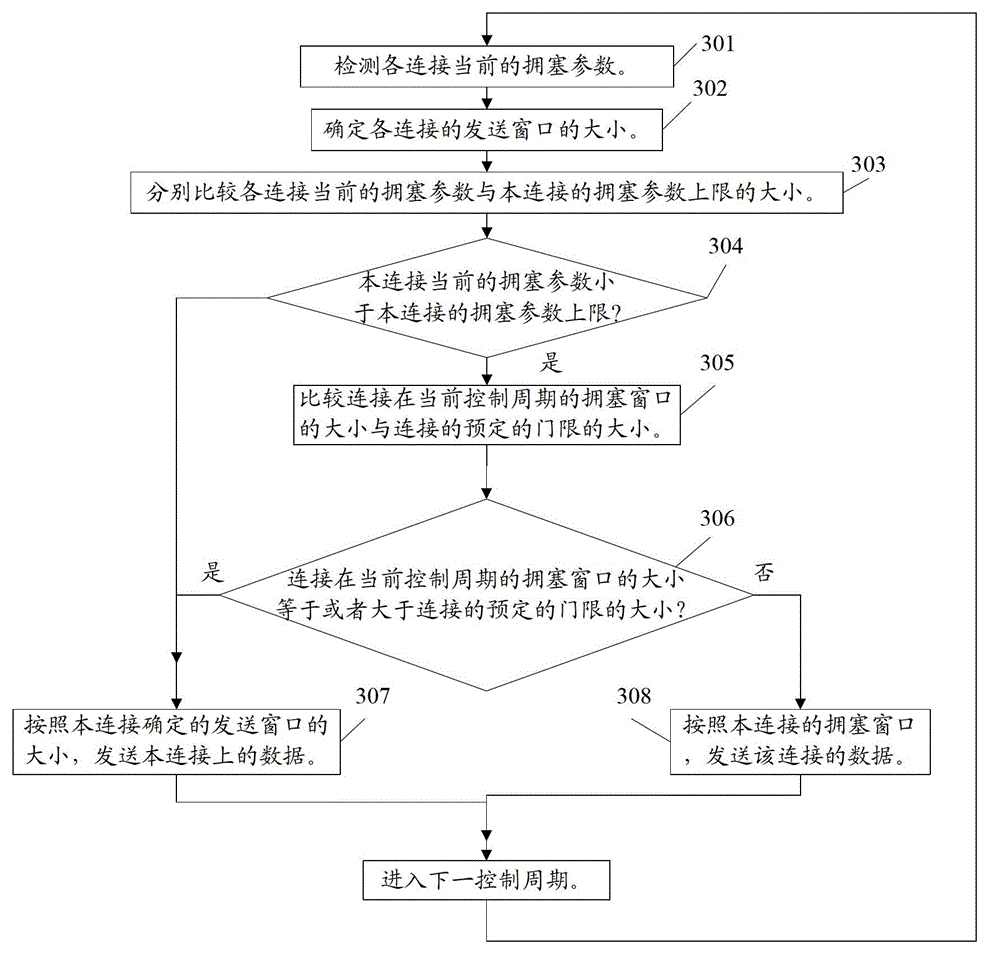
[0070] see image 3 As shown, the difference between the data transmission control method provided in this embodiment and Embodiment 1 includes that the data transmission control method in this embodiment includes the following steps:

[0071] Step 301: Detect the current congestion parameters of each connection.

[0072] It is the same as step 201 in Embodiment 1.

[0073] Step 302: Determine the size of the sending window of each connection.

[0074] It is the same as step 202 in Embodiment 1.

[0075] Step 303: Compare the current congestion parameter of each connection with the upper limit of the congestion parameter of this connection.

[0076] It is the same as step 203 in Embodiment 1.

[0077] Step 304: If the current congestion parameter of the current connection is smaller than the upper limit of the congestion parameter of the current connection, execute step 307; otherwise, execute step 305.

[0078] If the current congestion parameter of one or several connec...

Embodiment 3

[0090] see Figure 4 As shown, the data transmission control method provided by this embodiment is different from Embodiments 1 and 2 in that, in this embodiment, the size of the sending window of each connection can be determined according to the following technical solution. The method for determining the size of the sending window mainly includes the following processes:

[0091] Step 401: Detect the total number of current connections of the network sending device.

[0092] In this embodiment, the total number of current connections of the network sending device (marked as N) is regularly detected, so that in the next control cycle (marked as T), the sending window of each connection is determined according to the total number of current connections determined by the current detection the size of.

[0093] Step 402: Determine the egress bandwidth target value of the sending device in the network.

[0094]In this step, the egress bandwidth target value B can also be fixe...


PUM


Abstract

The invention relates to the field of communication and discloses a control method, a control device and a computer system for data transmission. The control method comprises the following steps of: detecting the current jam parameter of each connection; determining the size of a sending window of each connection; judging that the connection is in a non-jam state at present if the jam parameter of any connection is smaller than a top jam parameter limit of the current connection, sending data of the connection according to the size of the sending window of the connection in a current control period, and returning to the step of detecting the current jam parameter of each connection; and judging that the connection is in a jam state at present if the jam parameter of any connection is equal to or greater than the top jam parameter limit of the current connection, respectively sending data of the connection according to the size of the sending window of the connection in the current control period, and returning to the step of detecting the current jam parameter of each connection. With the adoption of the technical scheme, the stability of data transmission is improved and the bandwidth utilization is increased.

Description

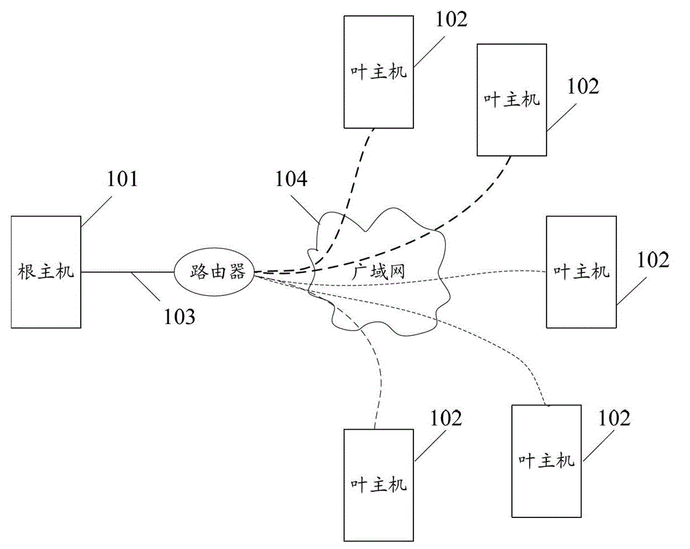
technical field [0001] The invention relates to the communication field, in particular to a data transmission control method and device and a computer system. Background technique [0002] With the development of communication technology, data transmission is an important component of the current communication network. In the network, data transmission is completed through the network sending device, and in the network topology, a network sending device is often connected to multiple peers. A network The sending device performs a data sending service for multiple connections. [0003] figure 1 For a common structural diagram of a data transmission system that implements multiple connections on a bandwidth-limited network link, see figure 1 As shown, the network sending device (also called the root host 101) is connected to the opposite end (also called the leaf host 102), and the root host 101 and each leaf host 102 share the trunk link 103 (the trunk link 103 is relativel...

Claims


Application Information

Patent Timeline
IPC IPC(8): H04L1/00H04L12/56
Inventor 扶柏成曾邵阳
Owner HUAWEI TECH CO LTD
Learn More