
Uninterruptible power supply with multiple energy redundancies

A multi-energy, energy technology, applied in emergency power supply arrangement, renewable energy integration, current collectors and other directions, can solve the problems of difficult restart, large loss of mains power, failure to restore equipment under natural conditions, etc., to improve energy utilization Efficiency, reduced operating losses, and the effect of extending the range of applications

Active Publication Date: 2014-04-16
ZHANGZHOU KEHUA ELECTRIC TECH CO LTD
View PDF5 Cites 0 Cited by
  • Summary
  • Abstract
  • Description
  • Claims
  • Application Information

AI Technical Summary

Problems solved by technology

[0004] 1. Not easy to restart after power failure
The input of the internal auxiliary power supply of the existing multi-energy input uninterruptible power supply basically comes from the mains or the storage battery. It can only be restarted when the power is turned on again or the battery voltage is higher than the undervoltage point. The equipment will automatically start and supply power when the natural conditions are not restored (such as the weather turns sunny or the wind blows again).
[0005] 2. It is not easy to save energy by choosing mains power first
The existing multi-energy input uninterruptible power supply basically uses mains power as the main power supply energy source in the priority selection of input energy, and solar energy, wind energy, etc. as supplementary energy. Full use
[0006] 3. Energy input expansion is not easy to achieve
The existing multi-energy input uninterruptible power supply basically uses DC input, directly connects the energy input to the DC bus in parallel, and does not configure a separate voltage stabilization isolation circuit. The output of the selected new energy equipment must meet the bus voltage requirements, which is bound to Limit the selection range of new energy equipment

Method used


Image

  • Uninterruptible power supply with multiple energy redundancies
  • Uninterruptible power supply with multiple energy redundancies

Examples


Embodiment Construction

[0026] In order to make the object, technical solution and advantages of the present invention clearer, the present invention will be further described in detail below through specific embodiments and related drawings.

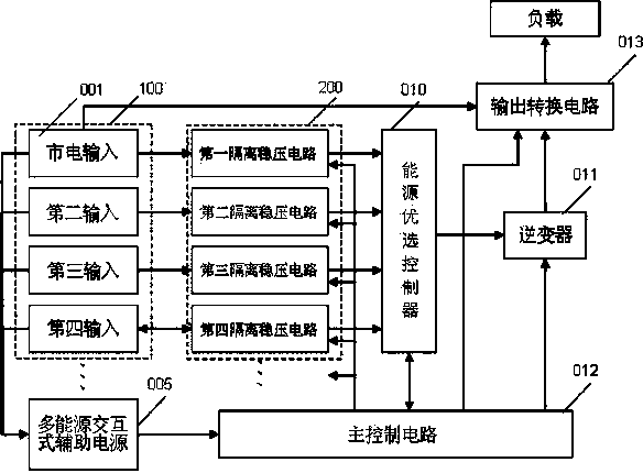
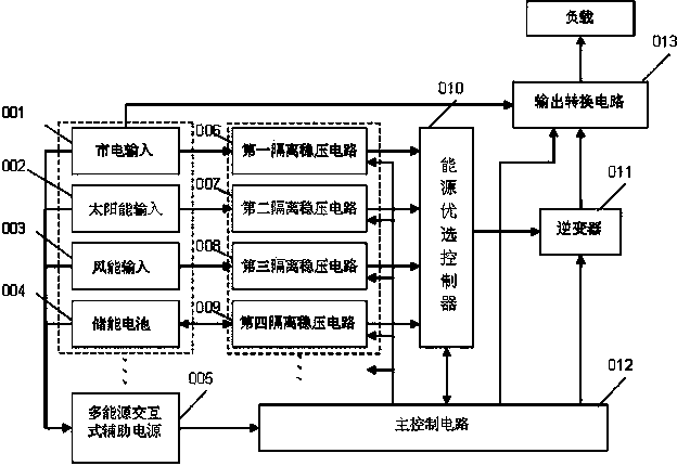
[0027] like figure 1 Shown is the system structure connection diagram of the present invention. Specifically, the energy input module 100 includes at least two energy inputs including the mains input 001, one output of each energy input is connected to the corresponding isolated voltage regulator circuit 200, and the other output is connected to the multi-energy interactive auxiliary power supply 005 connection, wherein the output of the mains input 001 is also connected to the output conversion circuit 013; the output of the isolated voltage stabilizing circuit 200 is connected to the energy optimal controller 010; the output of the main control circuit 012 is respectively connected to the energy optimal controller 010 and the isolated voltage stabilizing cir...


PUM


Abstract

The invention relates to an uninterruptible power supply with multiple energy redundancies. The uninterruptible power supply with multiple energy redundancies comprises an energy input module, an isolated voltage stabilizing circuit, an energy optimization controller, an inverter, an output conversion circuit, a main control circuit and a multi-energy interactive auxiliary power source, wherein the energy input module comprises at least two paths of energy inputting including a mains supply inputting. As the mains supply, solar energy, wind energy and energy storage batteries are converted and controlled through various corresponding circuits, the uninterruptible power supply with multiple energy redundancies, disclosed by the invention, has the advantages of being capable of stabilizing the outputting voltage efficiently, overcoming single application that the uninterruptable power supply system only depends on the mains supply and the energy storage batteries efficiently, expanding the application range of the uninterruptible power supply, realizing uniform, efficient and rational distribution of multiple energy sources, achieving efficient utilization of new energies and complementation of advantages of the uninterruptible power supply, and realizing green and efficient energy really.

Description

technical field [0001] The invention relates to a power conversion device in the technical field of power electronics, in particular to a multi-energy redundant uninterrupted power supply. Background technique [0002] The main energy of the traditional uninterruptible power supply still comes from the conventional city power, and it is equipped with a battery as a backup energy storage. When the city power is normal, it is directly powered by the city power. When the city power is abnormal, the inverter converts the DC power stored in the battery into AC power. For use, even in today's widespread application of new energy technologies, this method of use has not been effectively improved, and this approach is somewhat incompatible with the energy-saving concept advocated today. [0003] In recent years, some enterprises have begun to launch power supply equipment related to new energy, such as solar grid-connected inverters, photovoltaic control inverter integrated machines...

Claims


Application Information

Patent Timeline
Patent Type & Authority Patents(China)
IPC IPC(8): H02J9/06H02J7/35
CPCY02B10/72Y02B10/70Y02B70/30Y02P90/50Y04S20/20
Inventor 曾奕彰陈四雄陈成辉苏先进
Owner ZHANGZHOU KEHUA ELECTRIC TECH CO LTD
Learn More