
Topological subnetting method of electromagnetic transient simulation containing switching characteristic circuit

A technology for electromagnetic transient simulation and switching characteristics, which is applied in electrical digital data processing, special data processing applications, instruments, etc. to achieve the effect of small network scale, optimized real-time computing performance, and increased computing speed

Active Publication Date: 2012-10-24
CHINA ELECTRIC POWER RES INST +1
View PDF2 Cites 20 Cited by
  • Summary
  • Abstract
  • Description
  • Claims
  • Application Information

AI Technical Summary

Problems solved by technology

[0002] Time-domain simulation has become an important tool for power system analysis, design and research. With the wide application of power electronics technology, flexible AC transmission, high-voltage direct current Energy generation equipment generally needs to be connected to the grid through power electronic converters, and the network topology of power electronic switches, which is essentially changing with time, poses new requirements and challenges for traditional power system time domain simulation. Especially in the real-time simulation of electromagnetic transients, on the premise of ensuring the real-time performance of the calculation, it is a thorny technical difficulty to calculate the power electronic switching action at frequent and non-full-step long-term points

Method used


Image

  • Topological subnetting method of electromagnetic transient simulation containing switching characteristic circuit
  • Topological subnetting method of electromagnetic transient simulation containing switching characteristic circuit
  • Topological subnetting method of electromagnetic transient simulation containing switching characteristic circuit

Examples


Embodiment

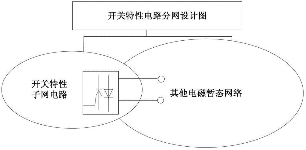
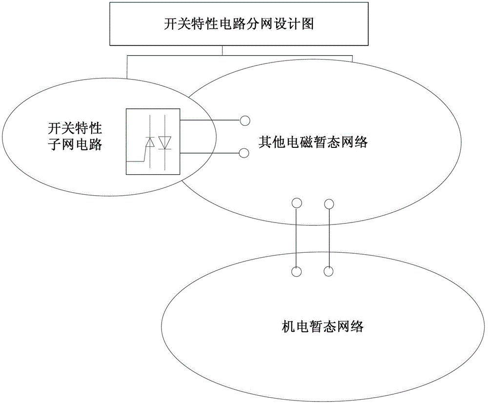
[0041] like image 3 and 4 as shown, image 3 It is a schematic diagram of the switching characteristic subnetwork subnetwork calculation principle diagram of the topology subnetwork method of the electromagnetic transient simulation of the circuit containing the switch characteristic provided by the present invention, Figure 4 It is a work flow diagram of the topology sub-network method of the electromagnetic transient simulation of the specific embodiment containing the switching characteristic circuit provided by the present invention, and the method includes the following steps:

[0042] 1. Start calculation;

[0043] 2. Divide the target power system into three parts: switch subnetwork and other electromagnetic subnetwork and electromechanical transient subnetwork, in which the other electromagnetic subnetwork part can be one subnetwork or can be decomposed into multiple subnetworks; involving power electronic switches, etc. The high-frequency switching circuit is cla...


PUM


Abstract

The invention relates to a topological subnetting method, in particular to a topological subnetting method of electromagnetic transient simulation containing a switching characteristic circuit. The method comprises the following steps that A, a target electric system is divided into two parts including a switching subnetwork and an electromagnetic subnetwork; B, the switching subnetwork and the electromagnetic subnetwork are respectively calculated in one electromagnetic step; C, the switching subnetwork and the electromagnetic subnetwork carry out data exchange; and D, next step electromagnetic transient calculation is carried out on the switching subnetwork and the electromagnetic subnetwork. The method has the advantages that an electric electronic switching network is designed into an independent electromagnetic network, the network scale is small, during the off-line / real-time switching calculation, only the subnetwork is subjected to iteration or interpolation calculation, other parts of the network do not participate in the iteration or interpolation calculation, the program modification on the electromagnetic network is reduced to the minimum, only few element models relevant to the electric electronic switch are modified, the switching calculation precision can also be ensured to the greatest degree, and in addition, the workload of the electromagnetic transient program parallelization calculation modification is favorably reduced.

Description

technical field [0001] The invention relates to a topological network division method, in particular to a topological network division method for electromagnetic transient simulation of circuits with switching characteristics. Background technique [0002] Time-domain simulation has become an important tool for power system analysis, design and research. With the wide application of power electronics technology, flexible AC transmission, high-voltage direct current Energy generation equipment generally needs to be connected to the power grid through power electronic converters, and the network topology of power electronic switches, which essentially changes with time, poses new requirements and challenges for traditional power system time-domain simulations. Especially in the real-time simulation of electromagnetic transients, on the premise of ensuring the real-time performance of the calculation, it is a thorny technical difficulty to calculate the power electronic switchi...

Claims


Application Information

Patent Timeline
Patent Type & Authority Applications(China)
IPC IPC(8): G06F17/50
Inventor 郑伟杰
Owner CHINA ELECTRIC POWER RES INST
Learn More