
Intensity estimation using binary sensor array with spatially varying thresholds

A sensor, binary technology, used in the field of imaging systems

Inactive Publication Date: 2015-03-04
NOKIA TECH OY
View PDF3 Cites 0 Cited by
  • Summary
  • Abstract
  • Description
  • Claims
  • Application Information

AI Technical Summary

Problems solved by technology

State-of-the-art binary sensor systems have only considered binary sensors with fixed thresholds

Method used


Image

  • Intensity estimation using binary sensor array with spatially varying thresholds
  • Intensity estimation using binary sensor array with spatially varying thresholds
  • Intensity estimation using binary sensor array with spatially varying thresholds

Examples


Embodiment Construction

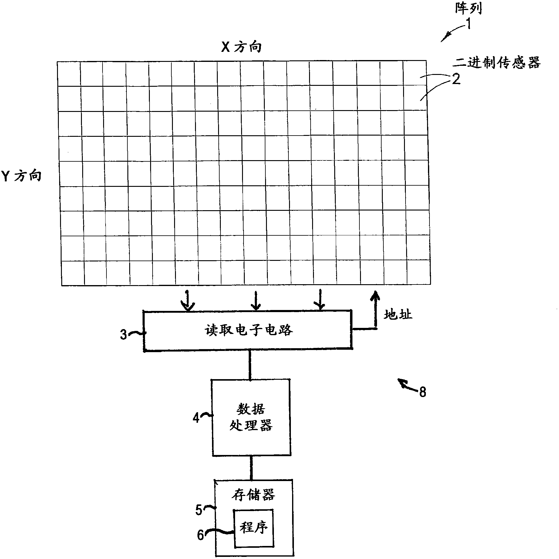
[0019] Exemplary embodiments of the present invention relate to digital camera light sensor technology, and more particularly, to binary type sensors ("receivers") with an exponentially high number of pixels ("bit cells"), The number may exceed 1 billion ("gigabit", 1×10 9 ). As noted above, "binary" means that each such sensor or receiver unit can have only two possible values: zero (unexposed) or one (exposed). Exemplary embodiments of the invention also relate to so-called sub-diffraction limited sensors or receivers. This means that the image projected on the receiver is not perfectly smooth, but more or less "fuzzy" compared to the size of the sensor element.

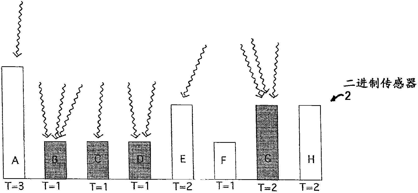
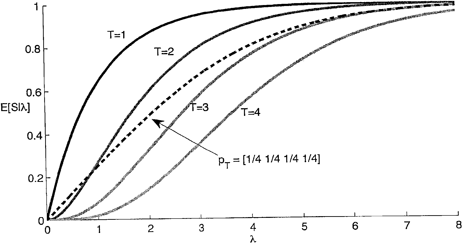
[0020] Exemplary embodiments of the present invention consider a more general situation than has been considered previously, where each binary sensor in the array has a fixed yet arbitrary threshold. The threshold of each binary sensor in the array can be assumed to be initially unknown.

[0021] Two different ...


PUM


Abstract

An apparatus includes an array containing N sub-diffraction limit light sensors each having an associated light absorption activation threshold for switching from a reset state to an activated state, where the light absorption activation values lie within a range of values. The apparatus further includes a processor connected with a memory including computer program code, where the memory and computer program code are configured to, with the processor, cause the apparatus at least to perform estimating an intensity of light that illuminates the array based on electrical outputs of the array.

Description

technical field [0001] Exemplary and non-limiting embodiments of the present invention relate generally to imaging systems, methods, apparatus, and computer programs, and more particularly, to imaging systems using an array of photosensors consisting of an array of photosensors whose The array produces a binary output signal. Background technique [0002] This section is intended to provide a background or context to the invention that is described in the claims. The description herein may include concepts that may be pursued, but not necessarily those that have been previously conceived, implemented or described. Therefore, unless otherwise indicated herein, what is described in this section is not prior art to the description and claims in this application and is not admitted to be prior art by inclusion herein. [0003] There has recently been interest in replacing traditional CCD (charge coupled device) photosensors with two-dimensional arrays of small binary photosens...

Claims


Application Information

Patent Timeline
Patent Type & Authority Patents(China)
IPC IPC(8): G01J1/46G01J1/18H04N5/3745
CPCG01J1/46H04N5/3745G01J1/18H04N25/00H04N25/46H04N25/77H01L27/146
Inventor T·里萨S·科斯基南M·维金科斯基T·玛基-玛蒂南
Owner NOKIA TECH OY
Learn More