Two-way compressing and shearing composite loading test device
A test device and composite loading technology, applied in the direction of measuring device, testing material strength by applying stable shear force, testing material strength by applying stable tension/compression, etc. Stretching and loading devices have complex structures and high costs, and achieve the effect of clear force transmission path, clear force value, and improved stability
- Summary
- Abstract
- Description
- Claims
- Application Information
AI Technical Summary
Problems solved by technology
Method used
Image
Examples
specific Embodiment approach 1
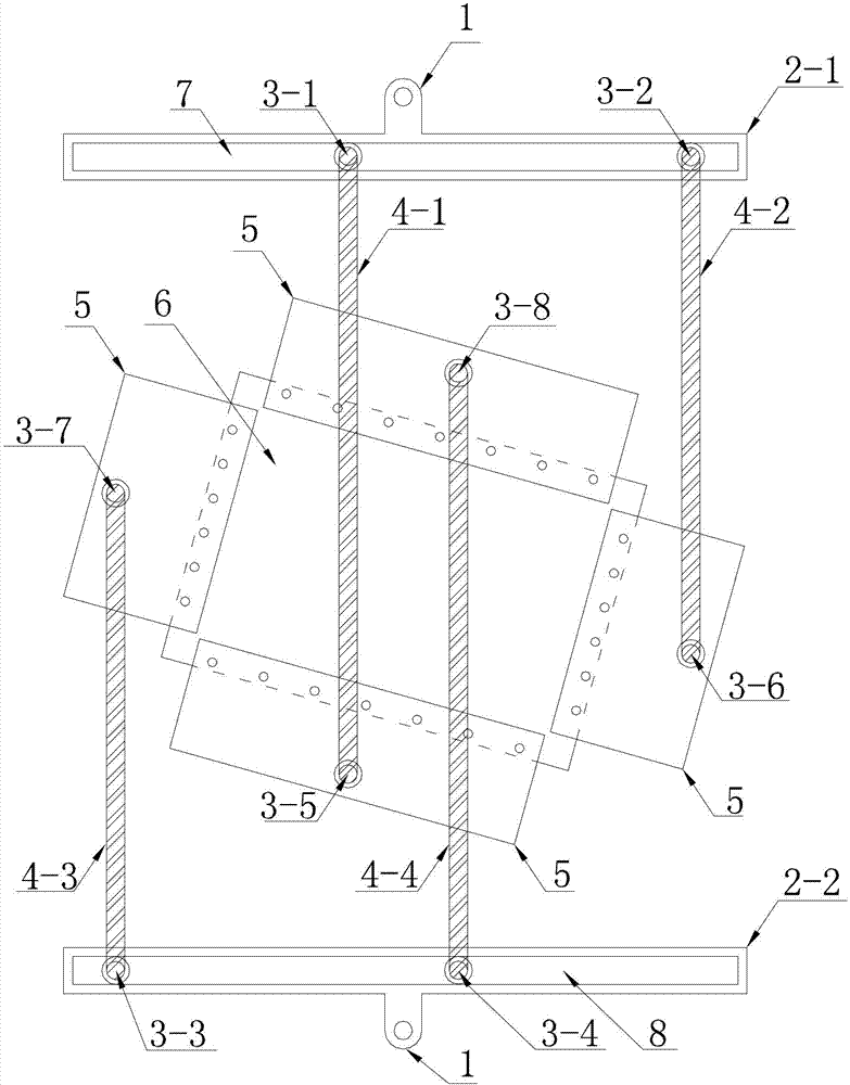
[0009] Specific implementation mode one: combine Figure 1-Figure 4 Describe this embodiment, the two-way compression-shear composite loading test device of this embodiment, the device includes a first distribution beam 2-1 and a second distribution beam 2-2, a first pin 3-1, a second pin 3-2, the third pin 3-3, the fourth pin 3-4, the fifth pin 3-5, the sixth pin 3-6, the seventh pin 3-7, the eighth pin 3- 8. Four pairs of dowel bars and four pairs of loading splints 5, each pair of dowel bars includes two dowel bars arranged in parallel, and the four pairs of dowel bars are respectively defined as the first pair of dowel bars 4-1, the second pair of dowel bars Dowel bars 4-2, the third pair of dowel bars 4-3 and the fourth pair of dowel bars 4-4, the first distribution beam 2-1 and the second distribution beam 2-2 are arranged in parallel, the first distribution beam 2 -1 is provided with the first pin shaft 3-1 and the second pin shaft 3-2, the second distribution beam 2-2...
specific Embodiment approach 2
[0011] Specific implementation mode two: combination figure 1 To illustrate this embodiment, a loading arm 1 is provided at the middle position of the first distribution beam 2-1 and the second distribution beam 2-2 of this embodiment, and this structure is used to connect a testing machine to apply tension. Other implementation manners are the same as the specific implementation manner 1.
specific Embodiment approach 3
[0012] Specific implementation mode three: combination figure 1 To illustrate this embodiment, the first distribution beam 2-1 of this embodiment has a first chute 7, and the first pin shaft 3-1 and the second pin shaft 3-2 slide in the first chute 7; There is a second chute 8 on the two distribution beams 2-2, the third pin 3-3 and the fourth pin 3-4 slide in the second chute 8, this structure can adjust the first pin 3- 1. The positions of the second pin shaft 3-2, the third pin shaft 3-3 and the fourth pin shaft 3-4 on the distribution beam. Other implementation manners are the same as the specific implementation manner 1.
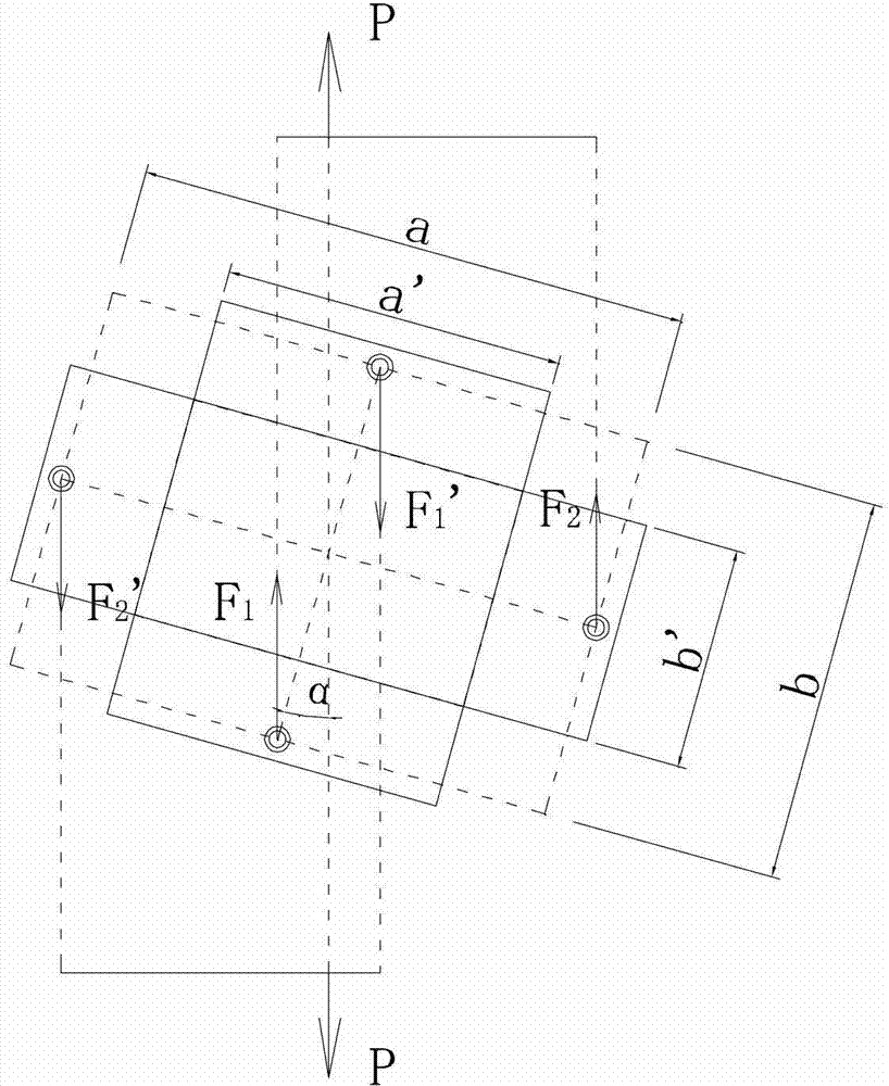
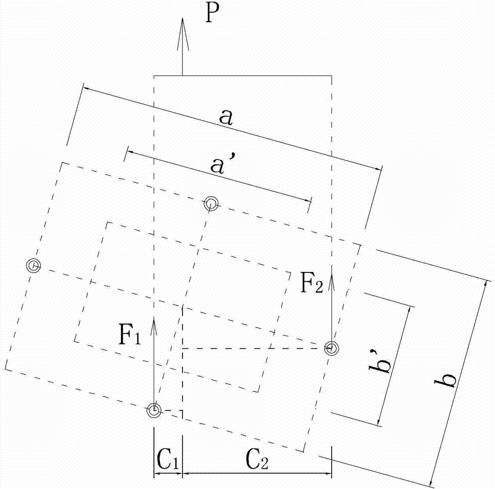
[0013] How it works: combined Figure 2-Figure 4 Explain the principle of the bidirectional compression-shear composite loading test device, the tensile force P of the testing machine, the deflection angle α of the test piece (that is, the connection line between the center of the fifth pin shaft 3-5 and the center of the eighth pin shaft 3-8 and the ...
PUM
 Abstract
Description
Claims
Application Information
 - Generate Ideas
- Intellectual Property
- Life Sciences
- Materials
- Tech Scout
- Unparalleled Data Quality
- Higher Quality Content
- 60% Fewer Hallucinations
Browse by: Latest US Patents, China's latest patents, Technical Efficacy Thesaurus, Application Domain, Technology Topic, Popular Technical Reports.
© 2025 PatSnap. All rights reserved.Legal|Privacy policy|Modern Slavery Act Transparency Statement|Sitemap|About US| Contact US: help@patsnap.com


