
A front longitudinal beam outer panel structure

A front longitudinal beam and plate structure technology, which is applied in the substructure, transportation and packaging, vehicle components, etc., can solve the problems of non-direct transmission path and low transmission efficiency, so as to optimize the transmission path, improve the collision performance, and improve the energy transmission. The effect of efficiency

Active Publication Date: 2016-08-03
SAIC GENERAL MOTORS +1
View PDF2 Cites 0 Cited by
  • Summary
  • Abstract
  • Description
  • Claims
  • Application Information

AI Technical Summary

Problems solved by technology

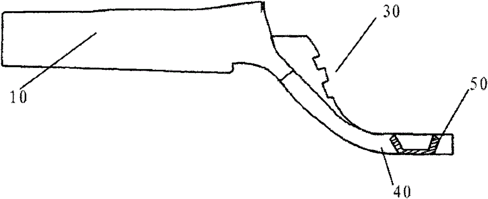
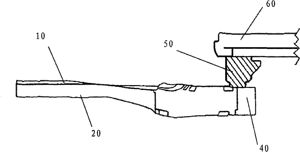
[0008] However, the connection angle between the box-shaped part 50 and the rear section 40 of the front side beam and the sill plate 60 is close to vertical, and the energy transmission path from the rear section 40 of the front side beam to the sill plate 60 is not direct, so the transmission efficiency is relatively low.

Method used


Image

  • A front longitudinal beam outer panel structure
  • A front longitudinal beam outer panel structure
  • A front longitudinal beam outer panel structure

Examples


Embodiment Construction

[0021] see Figure 4 and Figure 5 , which shows a preferred embodiment of a front longitudinal beam outer panel structure of the present invention, including a front longitudinal beam body, which includes a front longitudinal beam outer panel 1 and a front longitudinal beam inner panel 2, such as image 3 As shown, similar to the prior art, the front side member outer panel 1 and the front side member inner panel 2 of the present invention are also arranged in an approximately parallel manner in the front and rear direction of the vehicle, and extend rearward. It should be pointed out that in the present invention, Figure 4 and Figure 5 The left side of is the front direction of the vehicle; Figure 4 The upper side of is the direction outside the vehicle. Further, the rear section 4 of the front longitudinal beam outer panel 1 is fixedly connected to the door sill panel 6 and / or the front door hinge column 7 of the motor vehicle. In this embodiment, preferably, the fro...


PUM


Abstract

The invention relates to a front longitudinal beam outer plate structure of a motor vehicle. The front longitudinal beam outer plate structure comprises a front longitudinal beam body, wherein the front longitudinal beam body comprises a front longitudinal beam outer plate and a front longitudinal beam inner plate, the back section of the front longitudinal beam outer plate is mutually fixedly connected with a doorsill plate and / or a front door hinge pillar of the motor vehicle, a bending region is arranged at the middle section of the front longitudinal beam outer plate, and the front longitudinal beam outer plate on the bending region forms an angle alpha of less than 90 degrees with the trend of the front longitudinal beam body. According to the front longitudinal beam outer plate structure disclosed by the invention, when the collision of the front end occurs, one part of collision energy transferred by a front longitudinal beam can be effectively distributed to the front door hinge pillar and the doorsill plate before passing through the bending region, so that the front longitudinal beam outer plate structure disclosed by the invention can effectively optimize a transfer path of the energy, improve the transfer efficiency of the energy and further improve the collision performance of the whole vehicle.

Description

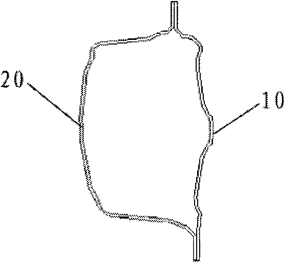
technical field [0001] The invention relates to a structure for absorbing and transmitting collision energy, in particular to a front longitudinal beam outer plate structure suitable for various vehicle body structures. Background technique [0002] The front side member structures in the prior art are generally arranged on both sides of the lower part of the engine compartment along the longitudinal direction of the vehicle. In the event of a frontal collision of the vehicle, the front side member is the most important carrier for absorbing and transmitting the collision energy. [0003] Such as figure 1 As shown, the front longitudinal beam is generally a closed cavity structure, which is divided into a front longitudinal beam outer panel 10 and a front longitudinal beam inner panel 20; [0004] Such as figure 2 and image 3 As shown, the front longitudinal beam outer panel 10 and the front longitudinal beam inner panel 20 extend rearward in an approximately parallel ...

Claims


Application Information

Patent Timeline
Patent Type & Authority Patents(China)
IPC IPC(8): B62D21/15
Inventor 张伟胡健
Owner SAIC GENERAL MOTORS
Learn More