
Detecting system for incremental encoder

A technology for incremental encoders and detection systems, applied in the field of incremental encoder detection systems, capable of solving the problems of low utilization of incremental encoder detection systems

Active Publication Date: 2012-10-10
BEIJING RUNKE GENERAL TECH
View PDF3 Cites 18 Cited by
  • Summary
  • Abstract
  • Description
  • Claims
  • Application Information

AI Technical Summary

Problems solved by technology

[0005] In view of this, the embodiment of the present invention provides an incremental encoder detection system to solve the problem of the existing incremental encoder detection system caused by the working limitations of high-precision encoders in special working environments in the prior art. The problem of low utilization

Method used


Image

  • Detecting system for incremental encoder
  • Detecting system for incremental encoder
  • Detecting system for incremental encoder

Examples


Embodiment Construction

[0028] The following will clearly and completely describe the technical solutions in the embodiments of the present invention with reference to the accompanying drawings in the embodiments of the present invention. Obviously, the described embodiments are only some, not all, embodiments of the present invention. Based on the embodiments of the present invention, all other embodiments obtained by persons of ordinary skill in the art without making creative efforts belong to the protection scope of the present invention.

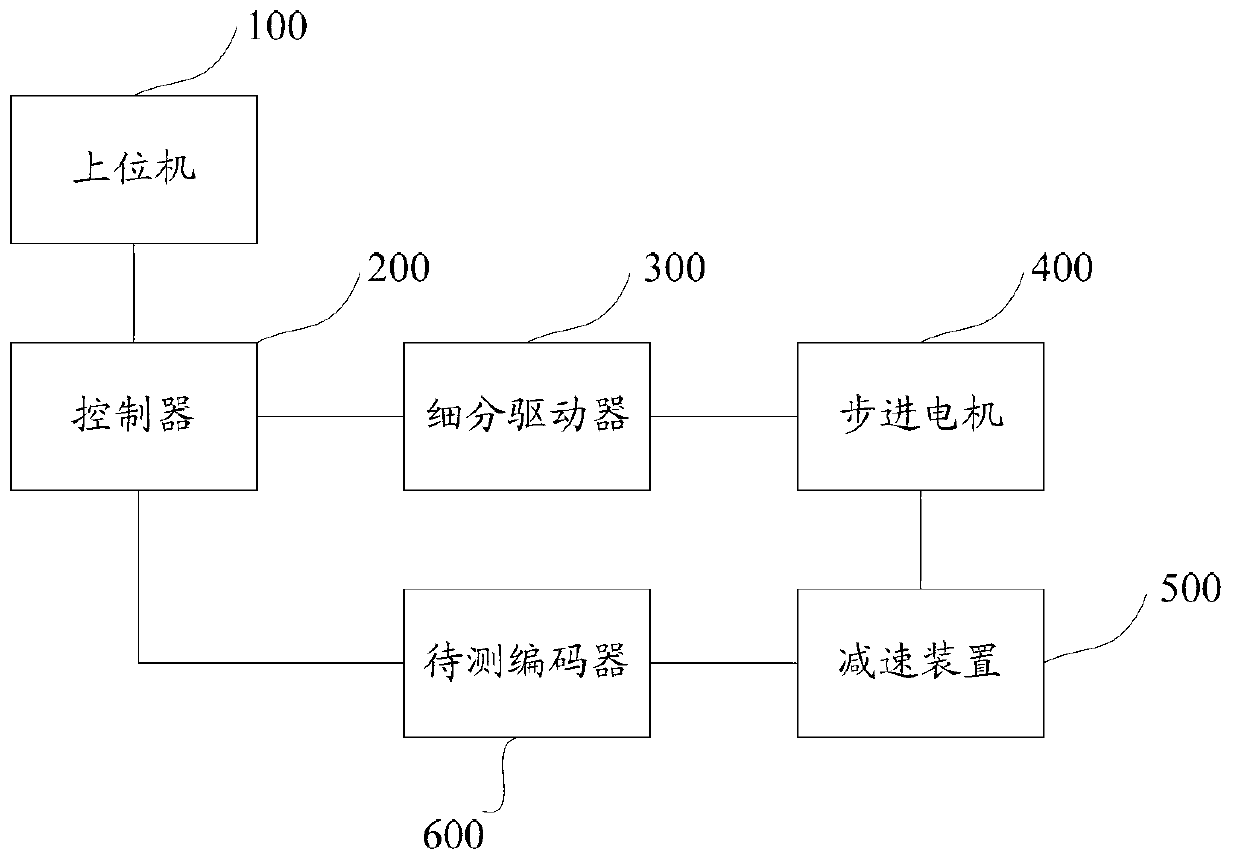
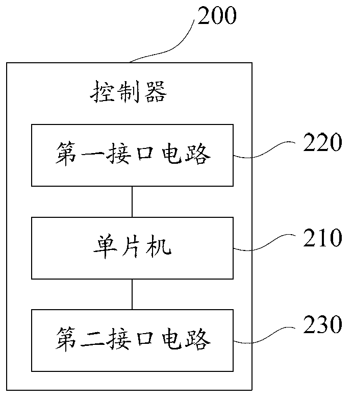
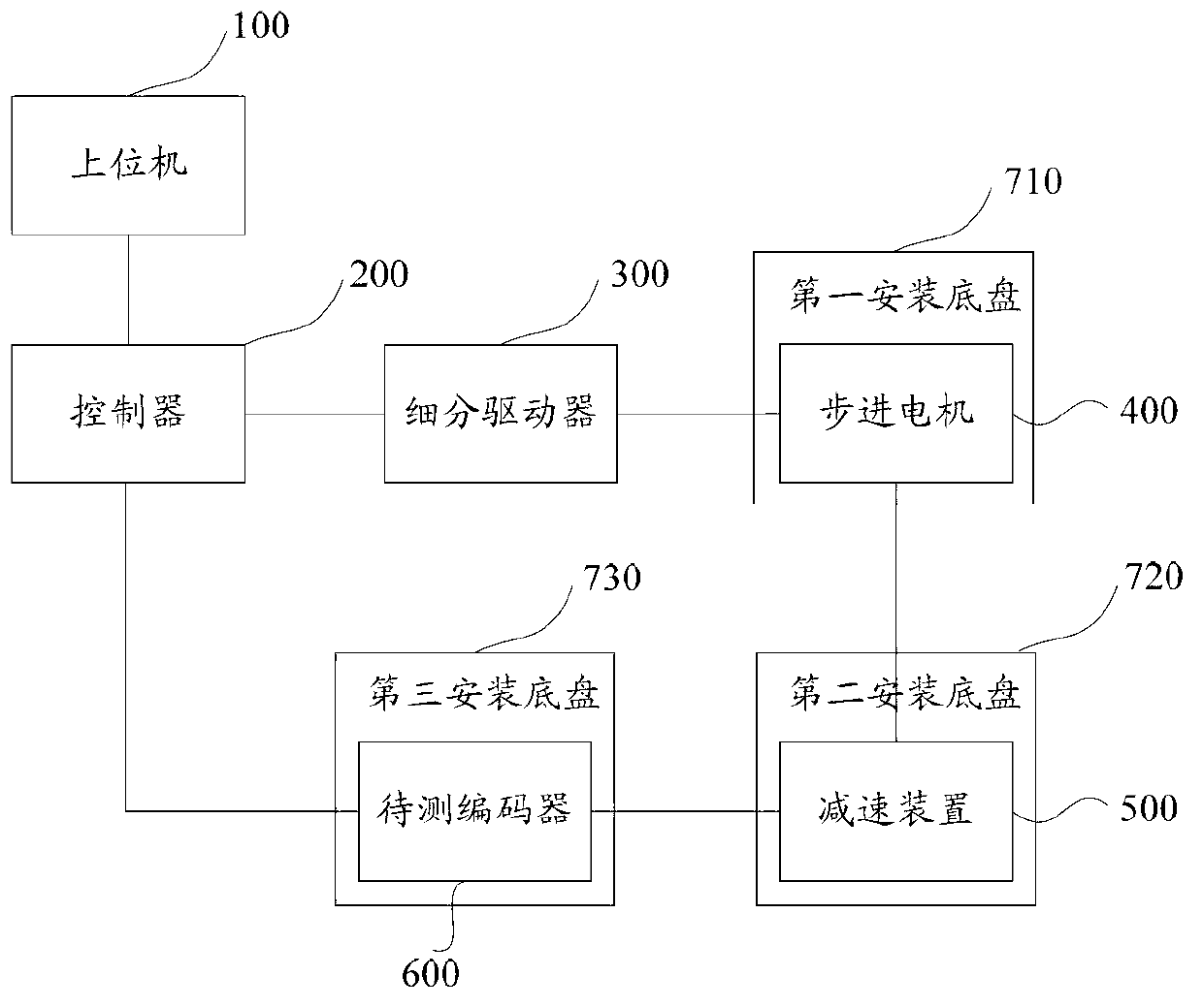
[0029] figure 1 A structural block diagram of an incremental encoder detection system provided by an embodiment of the present invention, refer to figure 1 , the system may include: a host computer 100, a controller 200, a subdivision driver 300, a stepping motor 400, a deceleration device 500 and an encoder to be tested 600; wherein, the host computer 100 is connected to the controller 200, and the controller 200 is respectively connected to The subdivision ...


PUM


Abstract

The invention provides a detecting system for an incremental encoder. The detecting system comprises an upper computer, a controller, a subdivision driver, a stepping motor, a speed reducing device and an encoder to be detected. The upper computer is used for transmitting a signal including angular displacement to the controller, comparing the angular displacement and actual rotary angular displacement of the encoder to be detected and judging the accuracy of the encoder to be detected. The controller is used for converting the angular displacement into the number n of corresponding pulses, transmitting a pulse signal to the subdivision driver and transmitting the signal including the angular displacement to the upper computer. The subdivision driver is used for performing microstep driving, generating pulse current and transmitting the pulse current to the stepping motor. The stepping motor is used for performing rotation according to received pulse current and outputting torque to drive the speed reducing device to rotate. The speed reducing device is used for driving the encoder to be detected to rotate. The encoder to be detected is used for converting self angular displacement in actual rotation into the number of the pulses and feeding back the number of the pulses to the controller. Compared with the prior art, the utilization rate is improved.

Description

technical field [0001] The invention relates to the field of encoder detection, in particular to an incremental encoder detection system. Background technique [0002] An encoder is a device that compiles and converts signals or data into signal forms that can be used for communication, transmission and storage. According to the working principle, encoders can be divided into two types: incremental encoders and absolute encoders. The incremental encoder can convert the displacement into a periodic electrical signal, and then convert the electrical signal into counting pulses, and use the number of pulses to represent the magnitude of the displacement. [0003] The accuracy of the incremental encoder is the basis of the control system. Before the incremental encoder is installed in the control system, it is necessary to test the accuracy of the incremental encoder to avoid the failure of the incremental encoder due to unqualified accuracy. poor performance of the control sys...

Claims


Application Information

Patent Timeline
Patent Type & Authority Applications(China)
IPC IPC(8): G01B21/22
Inventor 鞠彦伟
Owner BEIJING RUNKE GENERAL TECH
Learn More