


Quick Research
Generate reliable direction feasibility study reports for your R&D in just a few steps.

Technical Q&A
Discover and master advanced knowledge NOW. Basics, ideas, possibilities, all at once.

Find Solutions
As an expert in R&D theories, this can generate solutions to your technical problems instantly.

Evaluate Feasibility
Analyze your overall solution with one click, know your potential R&D risks in advance.

Monitor Landscape
Get weekly tech updates, stay abreast of the latest tech innovations and key insights.
Vibration device for precast tubular pile and precast tubular pile construction method
A technology of prefabricated pipe piles and vibrating devices, which is applied in sheet pile walls, foundation structure engineering, construction, etc., can solve the problems of large pile end resistance and pile side resistance, and difficult pile sinking, so as to improve piling capacity and reduce losses Effect
- Summary
- Abstract
- Description
- Claims
- Application Information
AI Technical Summary
Problems solved by technology
Method used
Image

Examples
Embodiment 1
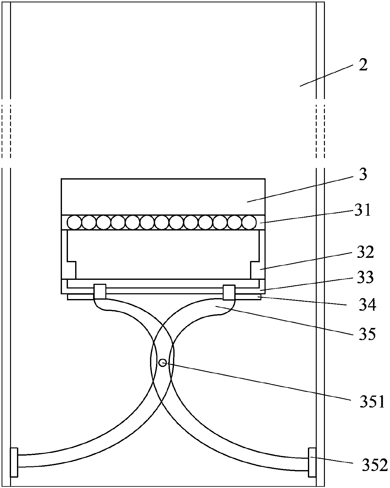
[0035] figure 2 A structural schematic diagram of a vibrating device for prefabricated pipe piles according to the present invention is shown. Such as figure 2 As shown, the vibration device 3 mainly includes a vibration component 31 , a hydraulic motor 32 and a slide rail 33 . The hydraulic motor 32 is supplied with high-pressure oil through known means such as an oil pipeline, and the hydraulic motor 32 drives the vibrating member 31 to vibrate.
[0036] The vibration device 3 also includes a pair of support arms 35 .
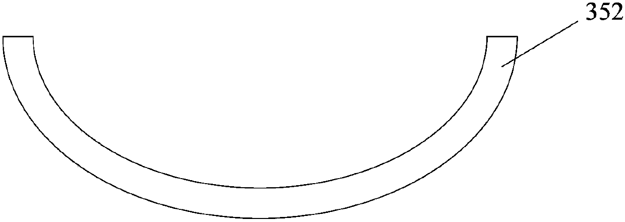
[0037] The upper ends of the pair of arms 35 are slidably fitted with the slide rails 33 , the lower ends of the pair of arms 35 are respectively provided with support plates 352 , and the middle parts of the pair of arms 35 are hinged by connecting parts 351 . The support plate 32 is preferably connected to the lower end of the support arm 35 by known means such as welding. The connection part 351 preferably adopts known connection elements such as pin...
Embodiment 2
[0042] Figure 4 It shows a top structural schematic view of another embodiment of the vibrating device for prefabricated pipe piles according to the present invention. Figure 5 shows along the Figure 4 Sectional view of line A-A. Such as Figure 4 and Figure 5 As shown, this embodiment is different from the first embodiment except that the support arm 36 is different, and other structures of the vibrating device 3 are the same. The number of the arms 36 of the vibrating device 3 involved in Embodiment 2 can be four, the four arms 36 are 90° to each other and the middle parts of the four arms 36 are respectively provided with openings 363, and the openings 363 are respectively Linked to the ring 361, the four arms 36 can rotate around the ring 361 like this. The opening portion 363 may preferably be provided as a circular hole portion.
[0043] In addition, at least four sets of limiting components 362 are provided on the circular ring 361 , and the limiting component...
PUM
 Abstract
Description
Claims
Application Information
 - R&D Engineer
- R&D Manager
- IP Professional
- Industry Leading Data Capabilities
- Powerful AI technology
- Patent DNA Extraction
Browse by: Latest US Patents, China's latest patents, Technical Efficacy Thesaurus, Application Domain, Technology Topic, Popular Technical Reports.
© 2024 PatSnap. All rights reserved.Legal|Privacy policy|Modern Slavery Act Transparency Statement|Sitemap|About US| Contact US: help@patsnap.com