Automatic feeding mechanism of E-type magnetic material vision inspection device

A visual inspection device and automatic feeding technology, which is applied to conveyor objects, transportation and packaging, etc., can solve the problems of unstable spacing, irregular arrangement, and difficult adjustment of feeding speed of E-type magnetic materials, so as to achieve stable spacing, The effect of neat feeding and stable and reliable work

Inactive Publication Date: 2014-01-01
HEILONGJIANG PATENT TECH DEV
View PDF8 Cites 0 Cited by
  • Summary
  • Abstract
  • Description
  • Claims
  • Application Information

AI Technical Summary

Problems solved by technology

[0005] In order to solve the problems that the feeding mechanism of the existing E-shaped magnetic material visual detection device has irregular arrangement, unstable spacing between E-shaped magnetic materials and difficult adjustment of feeding speed, the present invention further provides a Automatic feeding mechanism of visual inspection device

Method used


Image

  • Automatic feeding mechanism of E-type magnetic material vision inspection device
  • Automatic feeding mechanism of E-type magnetic material vision inspection device

Examples


specific Embodiment approach 1

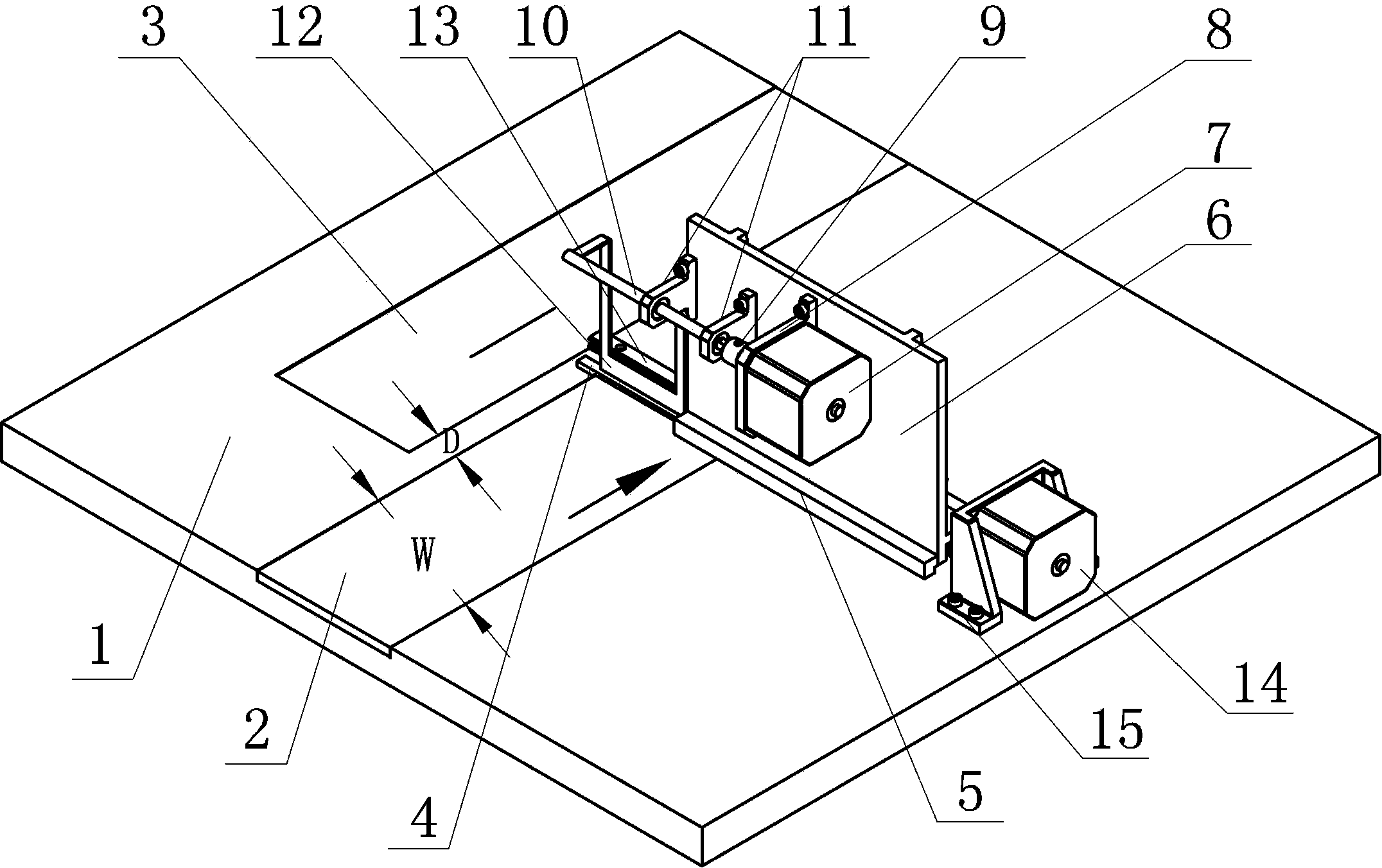
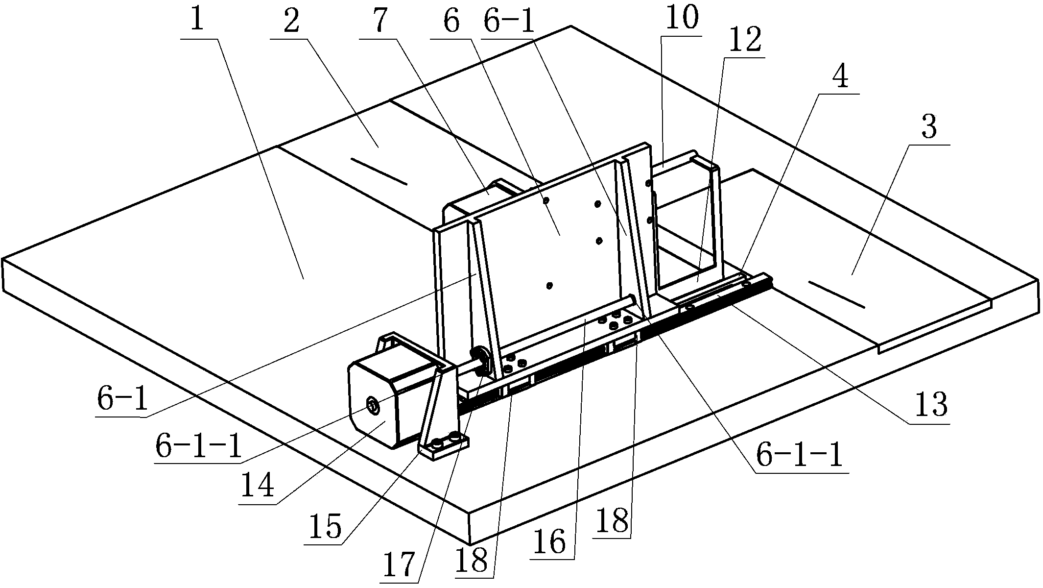
[0012] Specific implementation manner one: such as Figure 1~2 As shown, the automatic feeding mechanism for the E-shaped magnetic material visual inspection device of this embodiment includes a first conveyor belt 2, a second conveyor belt 3, a waiting baffle 4, a push rod 5, a translational support 6, a first Motor 7, first motor support 8, rotating shaft 10, rotatable baffle 12, linear guide 13, second motor 14, second motor bracket 15, screw 16, nut 17, at least one rotating shaft support frame 11 and two Two sliders 18, the second motor 14 is a stepping motor, the first conveyor belt 2 and the second conveyor belt 3 are arranged in parallel and staggered on the working table 1, and the waiting baffle 4 is fixed across the end of the first conveyor belt 2 On the work surface 1, the linear guide 13 is fixed on the work surface 1 and is arranged adjacent to and parallel to the baffle 4, two sliding blocks 18 are installed on the linear guide 13 in turn, and the lower end surf...

specific Embodiment approach 2

[0014] Specific implementation manner two: such as Figure 1~2 As shown, the width W of the first conveyor belt 2 and the second conveyor belt 3 in this embodiment are both 80 mm. This design can meet the loading requirements of all types of E-type magnetic materials within the detection range. The other components and connection relationships are the same as in the first embodiment.

specific Embodiment approach 3

[0015] Specific implementation manner three: such as Figure 1~2 As shown, in this embodiment, the distance D between the first conveyor belt 2 and the second conveyor belt 3 is 5 mm. Such a design can reduce the stroke of the translational support 6. Other components and connection relationships are the same as those in the first or second embodiment.


PUM


Abstract

The invention discloses an automatic feeding mechanism of an E-type magnetic material vision inspection device, relates to a feeding mechanism for E-type magnetic materials and aims to solve the problems of irregular arrangement, unstable distance between the E-type magnetic materials and difficulty in regulating the feeding speed of the feeding mechanism of the existing E-type magnetic material vision inspection device. Two sliding blocks are sequentially arranged on a linear guide rail; the lower end face of a translatable support is fixedly arranged on the upper end faces of the two sliding blocks along the length direction; a nut is arranged at the end face at one side of the translatable support; a second motor is fixedly arranged on a working table surface by a second motor bracket; one end of a screw is fixedly connected with an output shaft of the second motor; the screw is in threaded connection with the nut; the middle part of a rotating shaft is supported by a rotating shaft support frame; a rotatable baffle is fixedly arranged at the other end of the rotating shaft; the rotatable baffle and a waiting baffle are arranged in parallel up and down; and a push rod is fixedly arranged at the bottom of the end face at the other side of the translatable support along the length direction. The feeding mechanism disclosed by the invention is used for feeding the E-type magnetic materials.

Description

Technical field [0001] The invention relates to an automatic feeding mechanism for E-type magnetic materials, in particular to an automatic feeding mechanism for E-type magnetic materials visual inspection devices. Background technique [0002] The feeding mechanism used in the E-type magnetic material visual inspection device needs to neatly place the E-type magnetic material on the working conveyor belt at a certain interval. At present, the feeding mechanism of the E-type magnetic material visual inspection device is composed of two conveyor belts with different speeds and a splint that makes the magnetic materials neatly arranged. The center lines of the two conveyor belts are in a straight line, and the two conveyor belts are connected by a transition plate, and the E-shaped magnetic material is pushed to the transition plate through the waiting conveyor belt, and then the E-shaped magnetic material moves through the transition plate to a faster work On the conveyor belt, t...

Claims


Application Information

Patent Timeline
Patent Type & Authority Patents(China)
IPC IPC(8): B65G47/30B65G47/82
Inventor 李湛孙光辉于金泳刘宁高会军
Owner HEILONGJIANG PATENT TECH DEV
Why Eureka
Try Eureka