
Shift securing device for a multi-speed manual gearbox

A multi-speed transmission and stop device technology, which is applied in transmission control, components with teeth, belts/chains/gears, etc., can solve the problems of unsuitable transmissions and rare transmission structures, so as to save space and avoid stuck effect

Active Publication Date: 2012-10-03
ZF FRIEDRICHSHAFEN AG
View PDF15 Cites 3 Cited by
  • Summary
  • Abstract
  • Description
  • Claims
  • Application Information

AI Technical Summary

Problems solved by technology

[0009] All of the above-mentioned shift locks have a functional-technical disadvantage: the unconnected shift elements (shift forks and / or shift rockers) can only be moved or turned out of their neutral position by the connected shift elements. position is positively fixed
However, this type of construction of a transmission with shift forks guided axially displaceably on a selector shaft is relatively rare and is not suitable for more than three shift elements or selector forks in order to achieve compact dimensions. Gearbox for shaft shifter grooves

Method used


Image

  • Shift securing device for a multi-speed manual gearbox
  • Shift securing device for a multi-speed manual gearbox
  • Shift securing device for a multi-speed manual gearbox

Examples


Embodiment Construction

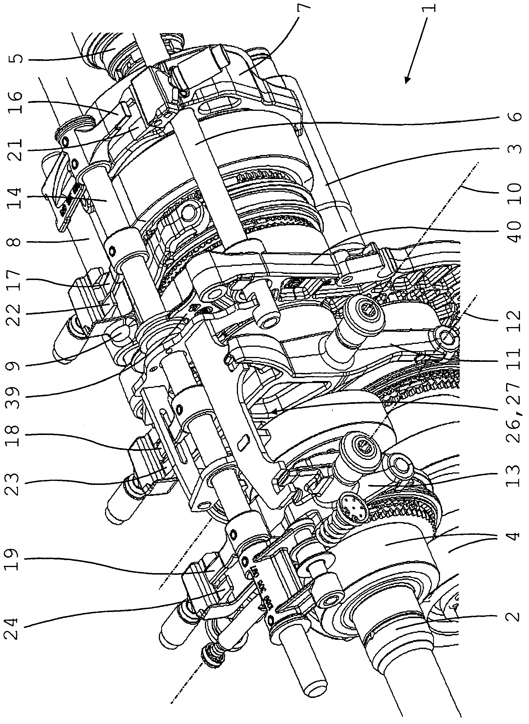
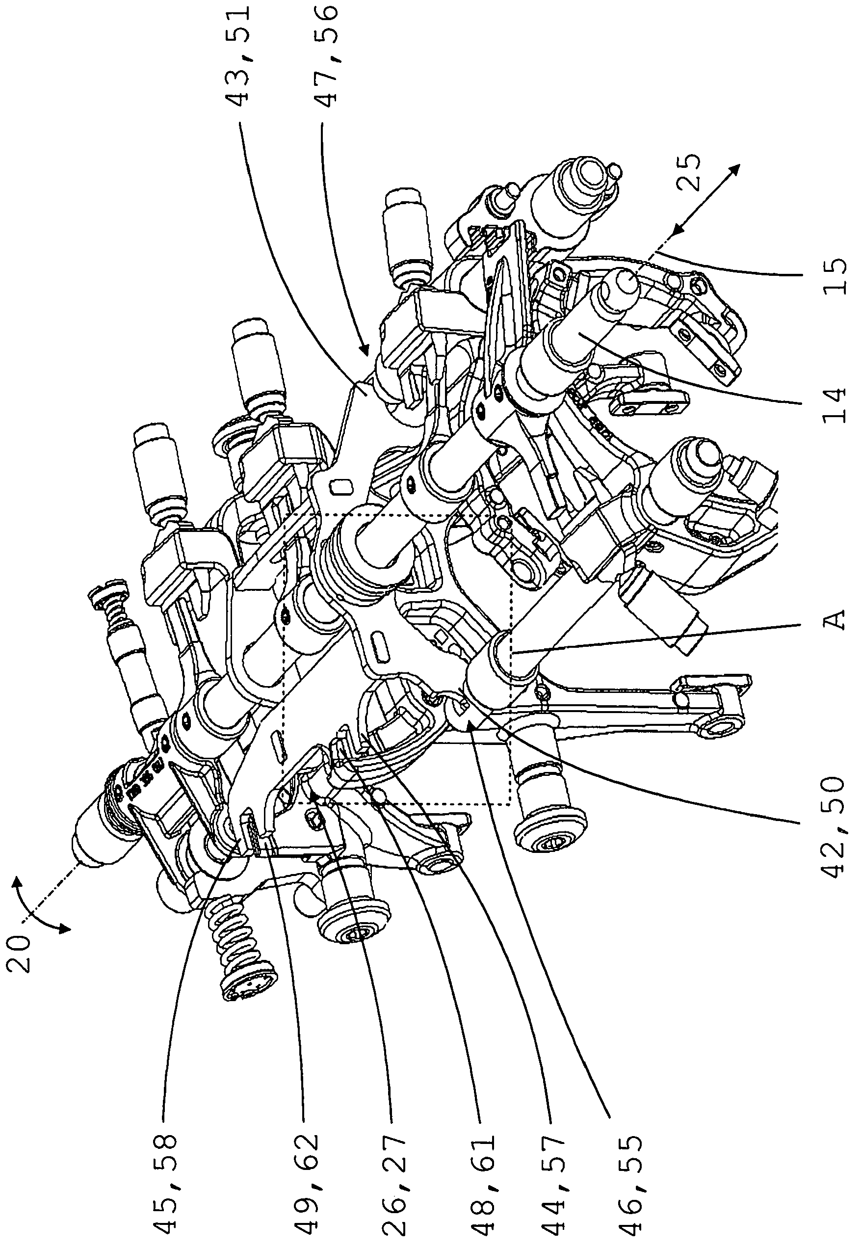
[0033] exist figure 1 with 2 The transmission 1, which is only partly shown in the figure, is designed as a layshaft structure and comprises an input shaft 2, a layshaft 3 arranged axially parallel to the input shaft, and an output shaft 5 arranged coaxially adjacent to the input shaft 2 , the countershaft is drivingly connected to the input shaft 2 via an input constant 4 configured as a pair of spur gears.

[0034] The transmission 1 has a total of seven switchable gears, that is, six forward gears G1 to G6 and one reverse gear R, wherein each of the six gears consists of a gear arranged between the layshaft 3 and the output shaft 5, each with a The fixed gear and a spur gear set with an idler gear that can be connected to the corresponding drive shaft 3, 5 via a gear clutch, and a high forward gear (G5 or G6) is configured as a drive shaft through the input shaft 2 and the output shaft 5 Direct connection to direct gear that can be switched on. The gear clutch of the rev...


PUM


Abstract

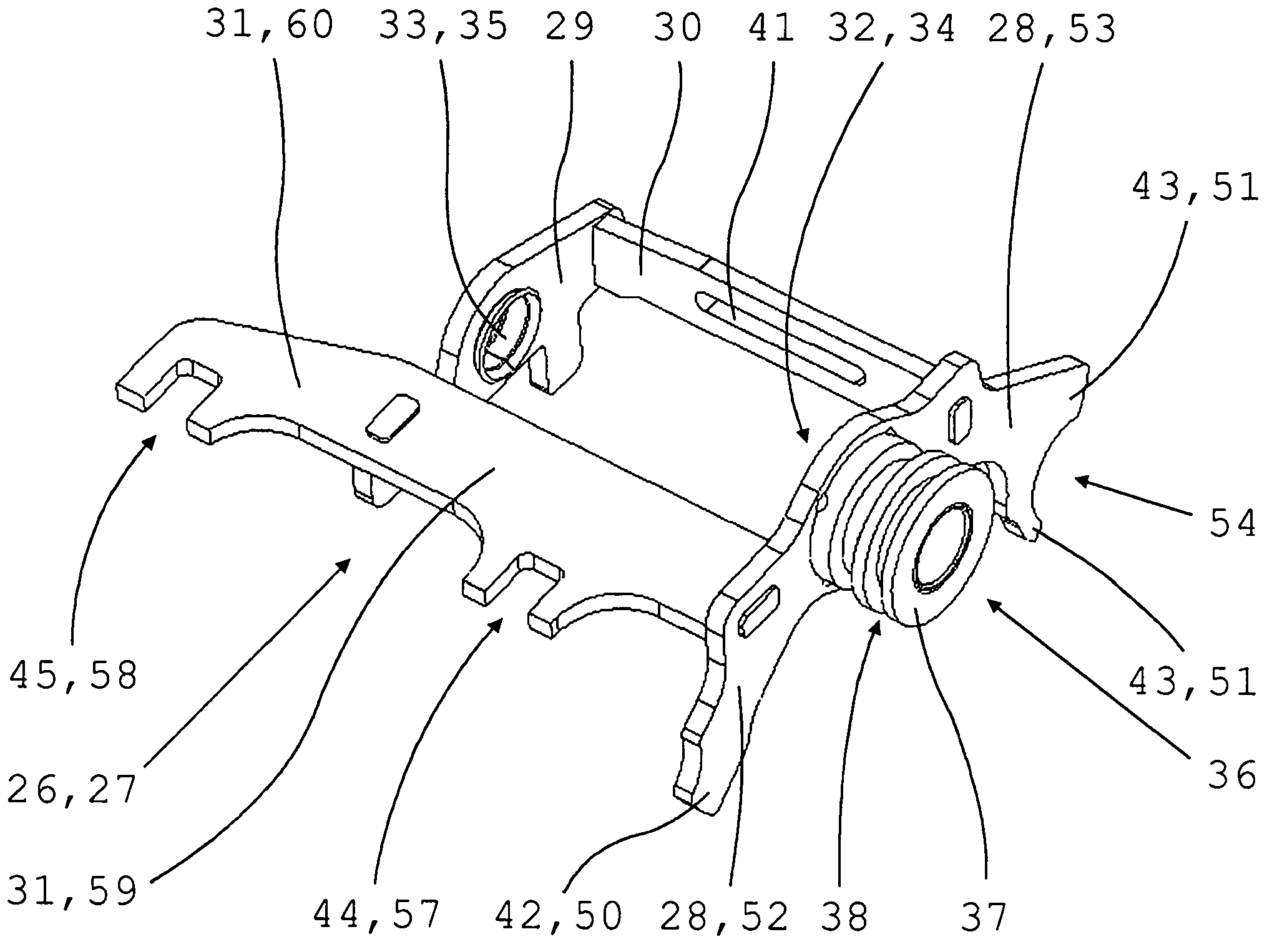
The invention relates to a shift securing device for a multi-speed manual gearbox which can be shifted by means of a gearshift shaft (14), which is disposed axially parallel to the transmission shafts (2, 3, 5) and is mounted so as to be axially movable and rotatable about the longitudinal axis (15) thereof and which can be selectively coupled by means of a respective associated shift finger (16, 17, 18, 19) to at least one shift fork (7, 9) guided on gearshift rod (6, 8) and / or to a shift crank (11, 13). Said shift securing device comprises a locking body (26), which is axially latched rigidly to the housing and can be rotated with the gearshift shaft (14) and on which locking elements (42, 43, 44, 45) are disposed for positive latching of the non-coupled shift forks (7, 9) and / or shift cranks (11, 13). In the shift securing device according to the invention, the locking body (26) is designed as a box frame (27) having at least two transverse supports (28, 29) and two longitudinal supports (30, 31), said frame comprising a bearing bore (32, 33) disposed in each of the transverse supports (28, 29), the gearshift shaft (14) being received in an axially movable manner in said bearing bores. Said box frame is connected non-rotatably to the gearshift shaft (14) by means of a driver (18) positively engaging peripherally with one of the longitudinal supports (30) and said box frame is axially latched rigidly to the housing by means of an axial bearing (36) disposed on one of the transverse supports (28).

Description

technical field [0001] The invention relates to a shift lock arrangement for a multi-speed transmission according to the features of the preamble of claim 1 . Background technique [0002] Multi-speed transmissions of motor vehicles are generally designed as countershafts and have at least two axially parallel drive shafts, which can be selectively brought into transmission with one another via a plurality of gears with different transmission ratios. In the case of a transmission provided for longitudinal installation in a motor vehicle, the drive shaft generally refers to the layshaft and the output shaft which are in driving connection with the input shaft via an input constant. In the case of a transmission provided for transverse installation in a motor vehicle, the drive shaft is usually formed by an input shaft and an output shaft. The gears are usually designed as spur gear pairs, which each have a fixed gear wheel that is fixedly arranged on one drive shaft and an i...

Claims


Application Information

Patent Timeline
Patent Type & Authority Applications(China)
IPC IPC(8): F16H63/36F16H63/34
CPCF16H63/3408F16H63/36Y10T74/20177Y10T74/19251Y10T74/2014
Inventor U·贝尔
Owner ZF FRIEDRICHSHAFEN AG
Learn More