An Interference Aligned Precoding Method Based on Stiefel Manifold

An interference alignment and precoding technology, applied in the multi-antenna transmission field of wireless communication, can solve problems such as low complexity, fast convergence speed, and large system overhead

Inactive Publication Date: 2015-08-12
UNIV OF SCI & TECH OF CHINA
View PDF4 Cites 0 Cited by
  • Summary
  • Abstract
  • Description
  • Claims
  • Application Information

AI Technical Summary

Problems solved by technology

[0003] The purpose of the present invention is to propose a transmitter unilaterally optimized interference alignment precoding method based on the Stiefel (Stiefel) manifold, to overcome the traditional method relying on the reciprocity of the channel to bring forward and reverse communication The defect of huge system overhead caused by repeated iterations of the link achieves the purpose of fast convergence, low complexity and high system capacity, and is applicable to both time division duplex and frequency duplex communication systems

Method used


Image

  • An Interference Aligned Precoding Method Based on Stiefel Manifold
  • An Interference Aligned Precoding Method Based on Stiefel Manifold
  • An Interference Aligned Precoding Method Based on Stiefel Manifold

Examples


Embodiment 1

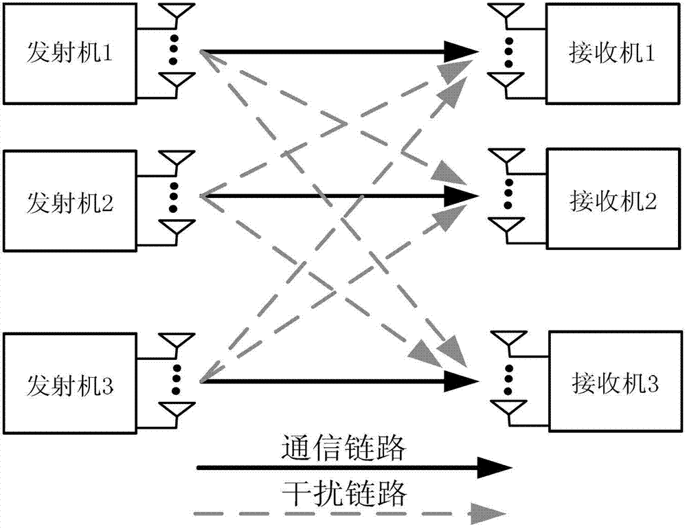
[0022] figure 1 A schematic block diagram of the flow principle of the system block diagram of the Stiefel manifold-based interference alignment precoding method of the present invention is given. The method of the present invention takes the minimum interference intensity in the signal space as the objective function, calculates the inner product expression and gradient direction of the objective function on the Stiefel manifold, and obtains the steepest falling edge on the Stiefel manifold , and finally realize the scheme of interference-aligned precoding.

[0023] The specific operation steps of the Stiefel manifold-based interference-aligned precoding method in this embodiment are as follows figure 1 as shown in:

[0024] Step 1. First initialize an arbitrary precoding matrix: V [1] ,...,V [K] ;

[0025] Step 2. Compute the covariance matrix Q [k] : In the multiple-input multiple-output communication system, the received signals of K users with M transmitting antenna...


PUM


Abstract

The invention discloses an interference alignment precoding method for transmitter unilateral optimization based on a Stiefel manifold, which is characterized in that the interference intensity in a minimum space signal is taken as an objective function, the objective function is reconfigured on the Stiefel manifold, an orthogonality constraint is removed, the inner product, the projection and steepest descent edge direction of the objective function on the Stiefel manifold are calculated, and interference aligned precoding is realized through a steepest descent edge algorithm based on the Stiefel manifold. As the dimensionality of the Stiefel manifold adopted in the interference alignment precoding method is smaller than that of a multidimensional complex space existing in a traditional optimization algorithm, the interference alignment precoding method has the advantages of quick convergence rate, low complexity, high system capacity and the like; and meanwhile, as only a transmitter needs to participate in the interference alignment precoding method, repeated iteration between a front communication link and a reverse communication link caused by the reason that transmitting and receiving ends must participate in an alignment as well as accompanied huge synchronism, feedback and other system overhead are avoided. The interference alignment precoding method is applicable to time-division and frequency duplex communication systems.

Description

technical field [0001] The invention belongs to the technical field of multi-antenna transmission in wireless communication, and in particular relates to a Stiefel manifold-based interference alignment precoding method. Background technique [0002] Interference alignment is a recently emerging multi-antenna transmission technology, which can greatly improve the capacity of wireless communication systems, so it has been widely valued and applied. According to "International Institute of Electronics and Electrical Engineers Information Theory Transactions" (IEEE Transactions on Information Theory, Vol.54, No.8, 2008, Page(s): 3425-3441), the core of interference alignment technology is to combine The interference signals of the data stream are aligned in one direction to reduce the dimension of the interference space, and the concept of degrees of freedom (DoF) is introduced. At present, the use of precoding to achieve interference alignment has been extensively studied as a...

Claims


Application Information

Patent Timeline
Patent Type & Authority Patents(China)
IPC IPC(8): H04L1/06
Inventor 张晨尹华锐卫国
Owner UNIV OF SCI & TECH OF CHINA
Why Eureka
Try Eureka