
Alternating-current contactor in low-voltage alternating-current control circuit and control method of alternating-current contactor

An AC contactor and control loop technology, applied in circuits, relays, electrical components, etc., can solve the problems of power failure, inability to operate normally, waste and other problems

Active Publication Date: 2012-10-03
西安润辉科技发展有限公司
View PDF5 Cites 12 Cited by
  • Summary
  • Abstract
  • Description
  • Claims
  • Application Information

AI Technical Summary

Problems solved by technology

The anti-sway auxiliary power supply module or restart device only considers local working conditions, but due to the large difference in power supply fluctuations (from 0% to 80% Ue), if there are many anti-sway auxiliary power modules connected, when the voltage is low A large number of devices continue to operate at low voltage. When the power supply is restored, the impact on the system is too large, which may cause a power outage due to protection actions and cause greater losses. If the system capacity is exceeded, it will also affect the safety of the power supply system; There are few auxiliary power supply modules, and there are few equipment to continue to operate when the voltage is high, which causes a lot of waste and cannot guarantee the normal operation of the process to the maximum extent; and the restart device cannot keep the AC contactor working when the power supply is abnormal, and the equipment has stopped running , the process flow has been interrupted, and restarting has no meaning

Method used


Image

  • Alternating-current contactor in low-voltage alternating-current control circuit and control method of alternating-current contactor
  • Alternating-current contactor in low-voltage alternating-current control circuit and control method of alternating-current contactor

Examples


Embodiment Construction

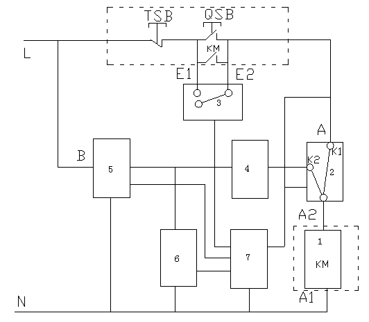
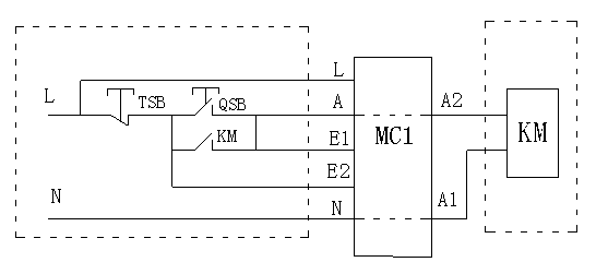
[0023] Such as figure 1 As shown, the intelligent control method for the AC contactor in the low-voltage AC control loop includes a loop control switch 2, a start-up switch 3, a current output control unit 4, a DC power conversion unit 5, an energy storage unit 6, a central control unit 7, and a power consumption unit. Equipment 1, the low-voltage AC voltage terminal L is loaded on both ends of the electrical equipment 1 through the self-contained switch circuit (AC contactor KM) of the electrical equipment 1 and the switch K1 of the control switch 2, and the self-provided switch circuit is connected with the running Switch 3; one voltage detection terminal of the central control unit 7 is electrically connected to the DC power conversion unit 5 for detecting the voltage of the input terminal B; the other circuit is electrically connected to the AC input voltage terminal A for detecting the voltage of the AC input voltage terminal A , the voltage terminal A and the voltage ter...


PUM


Abstract

The invention particularly relates to an alternating-current contactor in a low-voltage alternating-current control circuit and a control method of the alternating-current contactor. The alternating-current contactor comprises a circuit control switch, a starting run switch, a current output control unit, a direct-current power supply conversion unit, an energy storage unit, a central control unit and electric equipment, wherein a low-voltage alternating-current voltage end L is electrically connected with a K1 of the circuit control unit through an auxiliary switch circuit of the electric equipment; the auxiliary switch circuit is connected in parallel with the starting run switch; a one voltage detection end of the central control unit is electrically connected with the direct-current power supply conversion unit; another voltage detection end of the central control unit is electrically connected with an alternating-current output voltage end A; the voltage end A and a voltage end B are arranged at the two ends of the auxiliary switch circuit; and the central control unit is electrically connected with the circuit control switch, the starting run switch and the energy storage unit respectively. The working state of the electric equipment can be adjusted automatically, and the normal operation of the production process flow is ensured.

Description

technical field [0001] The invention relates to an intelligent control method for an AC contactor when the power supply is abnormal, in particular to an AC contactor and a control method in a low-voltage AC control loop. Background technique [0002] A large number of control components such as AC contactors are used in industrial control circuits. When the power supply is abnormal, the AC contactors will trip and affect the normal operation of the control circuit. At present, the anti-sway auxiliary power supply module is connected to the control circuit to prevent the impact of power fluctuations on the AC contactor or to restart the AC contactor when the power is restored. These control methods only consider the work of the AC contactor itself, and do not consider The impact of the AC contactor on the entire power supply system has not considered how to ensure the normal operation of the production process to the greatest extent from the production process. AC contactor ...

Claims


Application Information

Patent Timeline
Patent Type & Authority Applications(China)
IPC IPC(8): H01H47/00
Inventor 张勇
Owner 西安润辉科技发展有限公司
Learn More